Infiniti FX35 / FX45. Manual — part 391
DTC P0340, P0345 CMP SENSOR (PHASE)
EC-325
< SERVICE INFORMATION >
[VQ35DE]
C
D
E
F
G
H
I
J
K
L
M
A
EC
N
P
O
3.
If 1st trip DTC is detected, go to
If 1st trip DTC is not detected, go to next step.
4.
Maintaining engine speed at more than 800 rpm for at least 5 seconds.
5.
Check 1st trip DTC.
6.
If 1st trip DTC is detected, go to
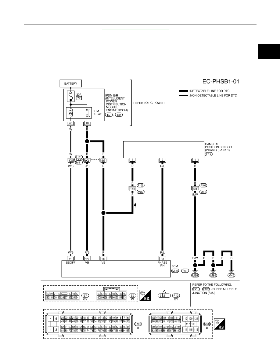
Wiring Diagram
INFOID:0000000001326153
BANK 1
TBWM1388E
EC-326
< SERVICE INFORMATION >
[VQ35DE]
DTC P0340, P0345 CMP SENSOR (PHASE)
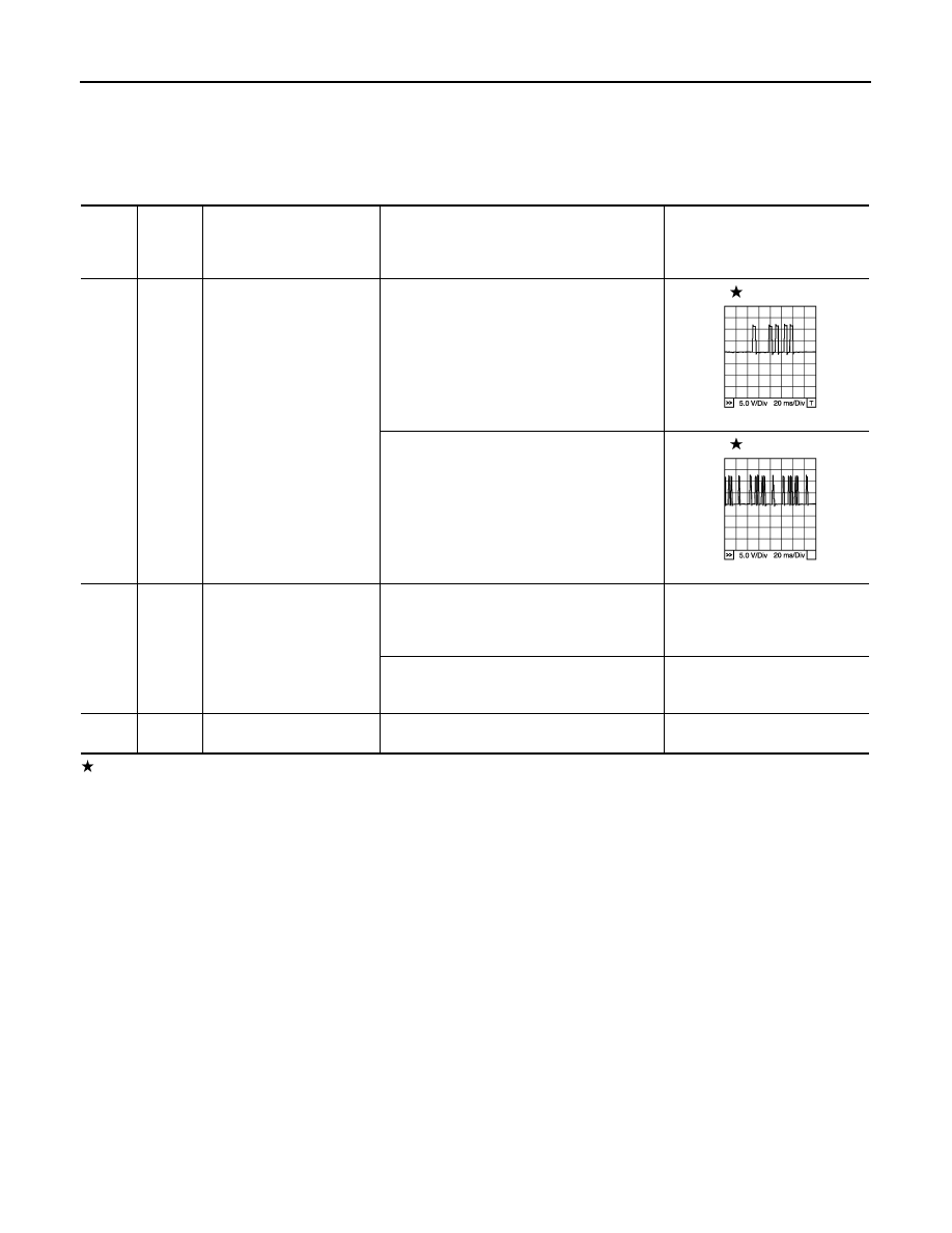
Specification data are reference values and are measured between each terminal and ground.
Pulse signal is measured by CONSULT-III.
CAUTION:
Do not use ECM ground terminals when measuring input/output voltage. Doing so may result in dam-
age to the ECM's transistor. Use a ground other than ECM terminals, such as the ground.
: Average voltage for pulse signal (Actual pulse signal can be confirmed by oscilloscope.)
TER-
MI-
NAL
NO.
WIRE
COLOR
ITEM
CONDITION
DATA (DC Voltage)
33
R/L
Camshaft position sensor
(PHASE) (bank 1)
[Engine is running]
• Warm-up condition
• Idle speed
NOTE:
The pulse cycle changes depending on rpm
at idle
1.0 - 4.0V
[Engine is running]
• Engine speed: 2,000 rpm
1.0 - 4.0V
111
W/B
ECM relay
(Self shut-off)
[Engine is running]
[Ignition switch: OFF]
• For a few seconds after turning ignition
switch OFF
0 - 1.5V
[Ignition switch: OFF]
• More than a few seconds after turning igni-
tion switch OFF
BATTERY VOLTAGE
(11 - 14V)
119
120
R
R/B
Power supply for ECM
[Ignition switch: ON]
BATTERY VOLTAGE
(11 - 14V)
PBIB1039E
PBIB1040E
DTC P0340, P0345 CMP SENSOR (PHASE)
EC-327
< SERVICE INFORMATION >
[VQ35DE]
C
D
E
F
G
H
I
J
K
L
M
A
EC
N
P
O
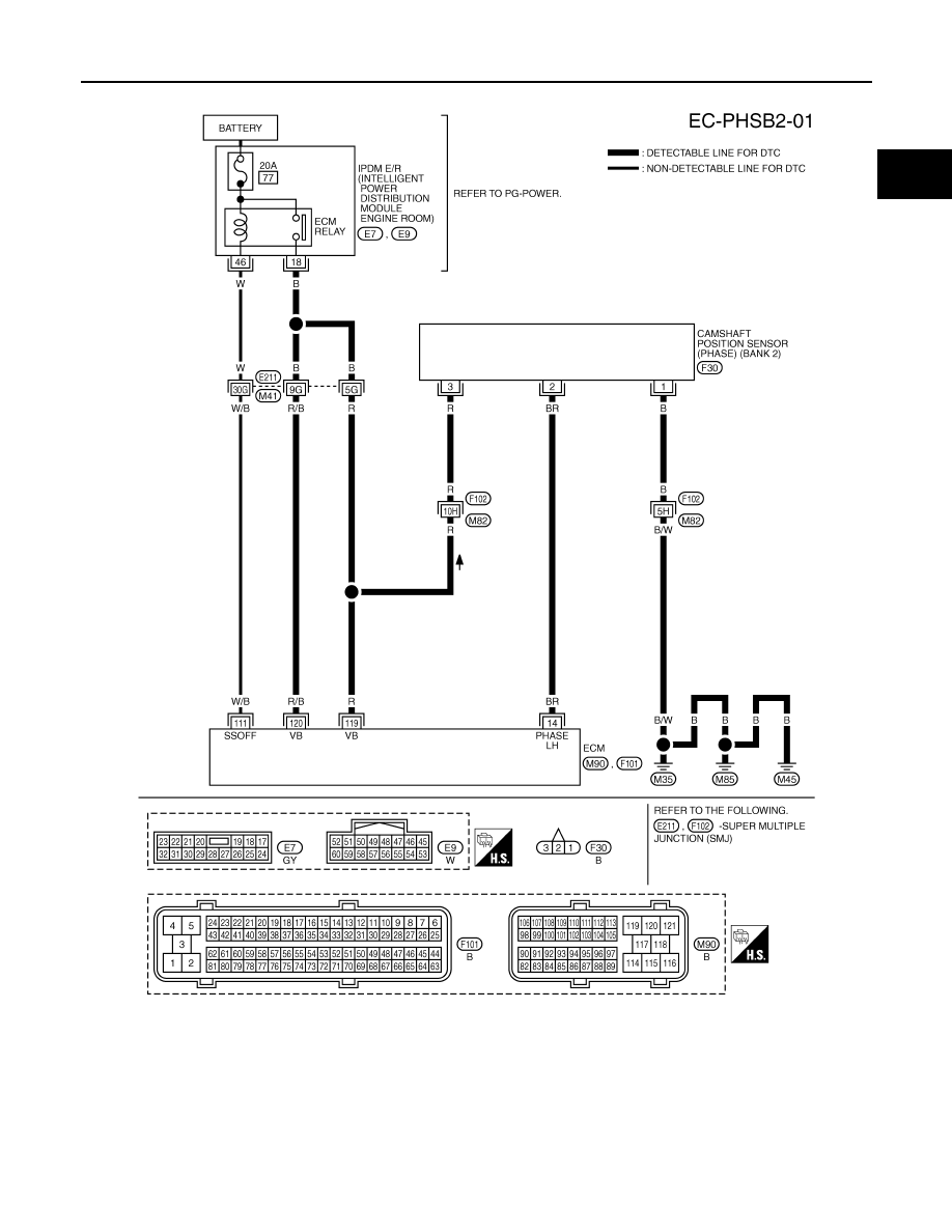
BANK 2
Specification data are reference values and are measured between each terminal and ground.
Pulse signal is measured by CONSULT-III.
CAUTION:
Do not use ECM ground terminals when measuring input/output voltage. Doing so may result in dam-
age to the ECM's transistor. Use a ground other than ECM terminals, such as the ground.
TBWM1389E
EC-328
< SERVICE INFORMATION >
[VQ35DE]
DTC P0340, P0345 CMP SENSOR (PHASE)
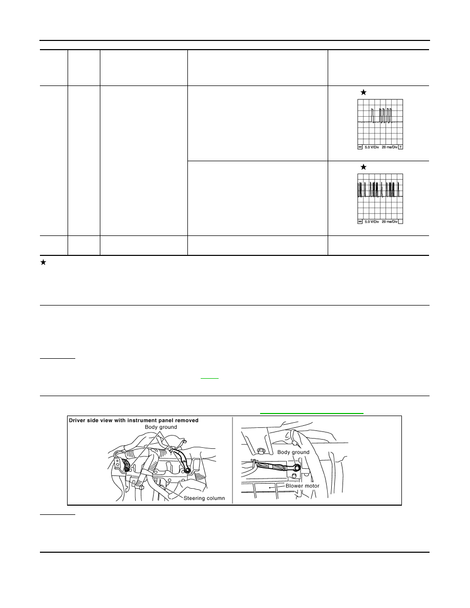
: Average voltage for pulse signal (Actual pulse signal can be confirmed by oscilloscope.)
Diagnosis Procedure
INFOID:0000000001326154
1.
CHECK STARTING SYSTEM
Turn ignition switch to START position.
Yes or No
Yes
>> GO TO 2.
No
>> Check starting system. (Refer to
.)
2.
CHECK GROUND CONNECTIONS
1.
Turn ignition switch OFF.
2.
Loosen and retighten ground screw on the body. Refer to
OK or NG
OK
>> GO TO 3.
NG
>> Repair or replace ground connections.
3.
CHECK CAMSHAFT POSITION (CMP) SENSOR (PHASE) POWER SUPPLY CIRCUIT
TER-
MI-
NAL
NO.
WIRE
COLOR
ITEM
CONDITION
DATA (DC Voltage)
14
BR
Camshaft position sensor
(PHASE) (bank 2)
[Engine is running]
• Warm-up condition
• Idle speed
NOTE:
The pulse cycle changes depending on rpm
at idle
1.0 - 4.0V
[Engine is running]
• Engine speed: 2,000 rpm
1.0 - 4.0V
119
120
R
R/B
Power supply for ECM
[Ignition switch: ON]
BATTERY VOLTAGE
(11 - 14V)
PBIB1039E
PBIB1040E
Does the engine turn over?
Does the starter motor operate?
PBIB2625E
Нет комментариевНе стесняйтесь поделиться с нами вашим ценным мнением.
Текст