Infiniti FX35 / FX45. Manual — part 729

TERMINOLOGY
GI-51
< SERVICE INFORMATION >
C
D
E
F
G
H
I
J
K
L
M
B
GI
N
O
P
***: Not applicable
Transmission control module
TCM
A/T control unit
Turbocharger
TC
Turbocharger
Vehicle speed sensor
VSS
Vehicle speed sensor
Volume air flow sensor
VAFS
Air flow meter
Warm up oxidation catalyst
WU-OC
Catalyst
Warm up oxidation catalytic converter sys-
tem
WU-OC system
***
Warm up three way catalyst
WU-TWC
Catalyst
Warm up three way catalytic converter sys-
tem
WU-TWC system
***
Wide open throttle position switch
WOTP switch
Full switch
NEW TERM
NEW ACRONYM /
ABBREVIATION
OLD TERM
GW-1
BODY
C
D
E
F
G
H
J
K
L
M
SECTION
GW
A
B
GW
N
O
P
CONTENTS
GLASSES, WINDOW SYSTEM & MIRRORS
SERVICE INFORMATION . . . . . . .
PRECAUTIONS . . . . . . . . . . . . ...
Precaution for Procedure without Cowl Top Cover
. ..
Handling for Adhesive and Primer . . . . . . ....
PREPARATION . . . . . . . . . . . . ...
Special Service Tool . . . . . . . . . . . .....
Commercial Service Tool . . . . . . . . . . ..
SQUEAK AND RATTLE TROUBLE DIAG-
NOSES . . . . . . . . . . . . . . . .
Work Flow . . . . . . . . . . . . . . . .....
Generic Squeak and Rattle Troubleshooting . . ....
Diagnostic Worksheet . . . . . . . . . . . ...
WINDSHIELD GLASS . . . . . . . . . .
Removal and Installation . . . . . . . . . . .
BACK DOOR WINDOW GLASS . . . . . .
Removal and Installation . . . . . . . . . . .
POWER WINDOW SYSTEM . . . . . . . ..
Component Parts and Harness Connector Loca-
tion . . . . . . . . . . . . . . . . . . ..
System Description . . . . . . . . . . . . .
CAN Communication System Description . . . ...
CAN Communication Unit . . . . . . . . . ...
Schematic . . . . . . . . . . . . . . . ...
Wiring Diagram - WINDOW - . . . . . . . . ..
Terminal and Reference Value for BCM . . . . .
Terminal and Reference Value for Power Window
Main Switch . . . . . . . . . . . . . . . .
Terminal and Reference Value for Front Power
Window Switch (Passenger Side) . . . . . . ...
CONSULT-III Function . . . . . . . . . . .
Work Flow . . . . . . . . . . . . . . . ...
Trouble Diagnosis Symptom Chart . . . . . . .
Check BCM Power Supply and Ground Circuit . ...
Check Power Window Main Switch Power Supply
Circuit . . . . . . . . . . . . . . . . . ..
Check Front Power Window Switch (Passenger
Side) Power Supply and Ground Circuit . . . . ..
Check Front Power Window Motor (Driver Side)
Circuit . . . . . . . . . . . . . . . . . ..
Check Front Power Window Motor (Passenger
Side) Circuit . . . . . . . . . . . . . . . .
Check rear Power Window Motor (LH) Circuit . . .
Check Rear Power Window Motor (RH) Circuit . ...
Check Limit Switch Circuit (Driver Side) . . . . ..
Check Limit Switch Circuit (Passenger Side) . . ..
Check Encoder Circuit (Driver Side) . . . . . .
Check Encoder Circuit (Passenger Side) . . . .
Check Door Switch . . . . . . . . . . . . ..
Check Front Door Key Cylinder Switch . . . . ...
Check Power Window Serial Link (Passenger
Side) . . . . . . . . . . . . . . . . . .
Check Power Window Lock Switch . . . . . . .
SIDE WINDOW GLASS . . . . . . . . .
Removal and Installation . . . . . . . . . . .
FRONT DOOR GLASS AND REGULATOR . .
Removal and Installation . . . . . . . . . . .
Disassembly and assembly . . . . . . . . . .
Inspection after Installation . . . . . . . . . ..
REAR DOOR GLASS AND REGULATOR . ...
Removal and Installation . . . . . . . . . . .
Disassembly and assembly . . . . . . . . . .
Fitting Inspection . . . . . . . . . . . . . .
INSIDE MIRROR . . . . . . . . . . . ...
Wiring Diagram - I/MIRR - . . . . . . . . . ...
Removal and Installation . . . . . . . . . . .
REAR WINDOW DEFOGGER . . . . . . ..
Component Parts and Harness Connector Loca-
tion . . . . . . . . . . . . . . . . . . ...
System Description . . . . . . . . . . . . ..
GW-2
CAN Communication Unit . . . . . . . . . ...
Schematic . . . . . . . . . . . . . . . ...
Wiring Diagram - DEF - . . . . . . . . . . ..
Terminal and Reference Value for BCM . . . . .
Terminal and Reference Value for IPDM E/R . . .
CONSULT-III Function (BCM) . . . . . . . ....
CONSULT-III Function (IPDM E/R) . . . . . ....
Work Flow . . . . . . . . . . . . . . . ...
Trouble Diagnosis Symptom Chart . . . . . . .
Check BCM Power Supply and Ground Circuit . ..
Check Rear Window Defogger Switch Circuit . ....
Check rear Window Defogger Power Supply Cir-
cuit . . . . . . . . . . . . . . . . . . ..
Check Rear Window Defogger Circuit . . . . ....
Check Door Mirror Defogger Power Supply Circuit
...
Check Driver Side Door Mirror Defogger Circuit . .
Check Passenger Side Door Mirror Defogger Cir-
cuit . . . . . . . . . . . . . . . . . . ..
Check Rear Window Defogger Signal . . . . .
Check Filament . . . . . . . . . . . . . ...
Filament Repair . . . . . . . . . . . . . ...
DOOR MIRROR . . . . . . . . . . . . .
Wiring Diagram - MIRROR - (Without Electric
Foldable Door Mirror) . . . . . . . . . . . ..
Schematic (With Electric Foldable Door Mirror) . ..
Wiring Diagram - MIRROR - (With Electric Fold-
able Door Mirror) . . . . . . . . . . . . . .
Trouble Diagnosis . . . . . . . . . . . . ...
Removal and Installation . . . . . . . . . . .
PRECAUTIONS
GW-3
< SERVICE INFORMATION >
C
D
E
F
G
H
J
K
L
M
A
B
GW
N
O
P
SERVICE INFORMATION
PRECAUTIONS
Precaution for Supplemental Restraint System (SRS) "AIR BAG" and "SEAT BELT
PRE-TENSIONER"
INFOID:0000000001612893
The Supplemental Restraint System such as “AIR BAG” and “SEAT BELT PRE-TENSIONER”, used along
with a front seat belt, helps to reduce the risk or severity of injury to the driver and front passenger for certain
types of collision. This system includes seat belt switch inputs and dual stage front air bag modules. The SRS
system uses the seat belt switches to determine the front air bag deployment, and may only deploy one front
air bag, depending on the severity of a collision and whether the front occupants are belted or unbelted.
Information necessary to service the system safely is included in the “SUPPLEMENTAL RESTRAINT SYS-
TEM” and “SEAT BELTS” of this Service Manual.
WARNING:
• To avoid rendering the SRS inoperative, which could increase the risk of personal injury or death in
the event of a collision which would result in air bag inflation, all maintenance must be performed by
an authorized NISSAN/INFINITI dealer.
• Improper maintenance, including incorrect removal and installation of the SRS, can lead to personal
injury caused by unintentional activation of the system. For removal of Spiral Cable and Air Bag
Module, see the “SUPPLEMENTAL RESTRAINT SYSTEM”.
• Do not use electrical test equipment on any circuit related to the SRS unless instructed to in this
Service Manual. SRS wiring harnesses can be identified by yellow and/or orange harnesses or har-
ness connectors.
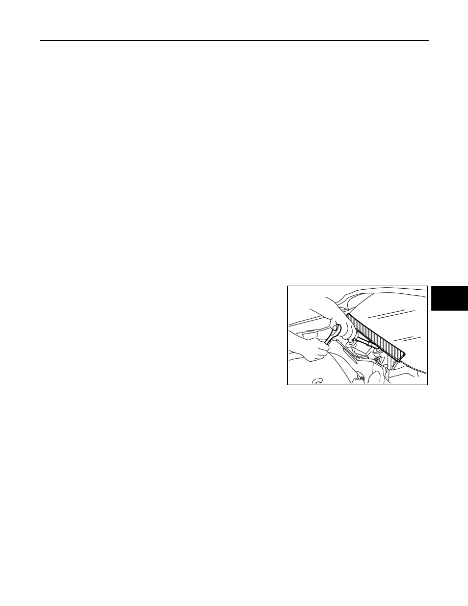
Precaution for Procedure without Cowl Top Cover
INFOID:0000000001612894
When performing the procedure after removing cowl top cover, cover
the lower end of windshield with urethane, etc.
Handling for Adhesive and Primer
INFOID:0000000001327954
• Do not use an adhesive which is past its usable date. Shelf life of this product is limited to six months after
the date of manufacture. Carefully adhere to the expiration or manufacture date printed on the box.
• Keep primers and adhesive in a cool, dry place. Ideally, they should be stored in a refrigerator.
• Open the seal of the primer and adhesive just before application. Discard the remainder.
• Before application, be sure to shake the primer container to stir the contents. If any floating material is found,
do not use it.
• If any primer or adhesive contacts the skin, wipe it off with gasoline or equivalent and wash the skin with
soap.
• When using primer and adhesive, always observe the precautions in the instruction manual.
PIIB3706J
Нет комментариевНе стесняйтесь поделиться с нами вашим ценным мнением.
Текст