Infiniti FX35 / FX45. Manual — part 766
TROUBLE DIAGNOSIS
LAN-41
< SERVICE INFORMATION >
[CAN]
C
D
E
F
G
H
I
J
L
M
A
B
LAN
N
O
P
0: Error at present, 1 – 39: Error in the past (Number means the number of times the ignition switch is turned OFF
→
ON)
*: 39 or higher number is fixed at 39 until the self-diagnosis result is erased.
LDW Camera Unit
0: Error at present, 1 – 39: Error in the past (Number means the number of times the ignition switch is turned OFF
→
ON)
*: 39 or higher number is fixed at 39 until the self-diagnosis result is erased.
Unified Meter and A/C Amp.
0: Error at present, 1 – 39: Error in the past (Number means the number of times the ignition switch is turned OFF
→
ON)
*: 39 or higher number is fixed at 39 until the self-diagnosis result is erased.
ABS Actuator and Electric Unit (Control Unit)
ITEM
CAN DIAG SUP-
PORT MNTR
Description
Normal
Error
PRSNT
PAST
PRSNT
PAST
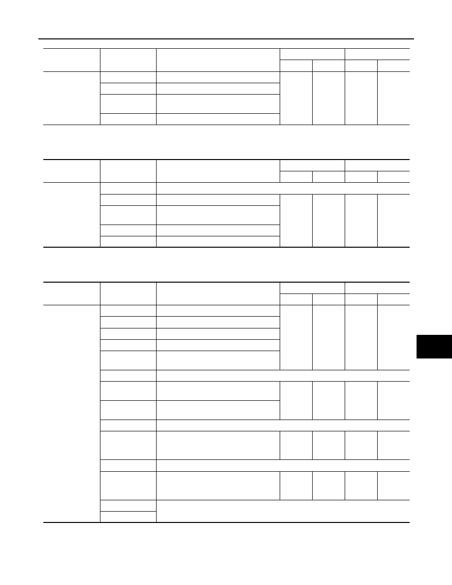
I-KEY
TRANSMIT DIAG
Signal transmission status
OK
OK
or
1 – 39
*
UNKWN
0
ECM
Signal receiving status from the ECM
METER/M&A
Signal receiving status from the unified
meter and A/C amp.
BCM/SEC
Signal receiving status from the BCM
ITEM
CAN DIAG SUP-
PORT MNTR
Description
Normal
Error
PRSNT
PAST
PRSNT
PAST
LKS
TRANSMIT DIAG
Not used even though indicated
ECM
Signal receiving status from the ECM
OK
OK
or
1 – 39
*
UNKWN
0
VDC/TCS/ABS
Signal receiving status from the ABS actu-
ator and electric unit (control unit)
BCM/SEC
Signal receiving status from the BCM
TCM
Signal receiving status from the TCM
ITEM
CAN DIAG SUP-
PORT MNTR
Description
Normal
Error
PRSNT
PAST
PRSNT
PAST
M&A
TRANSMIT DIAG
Signal transmission status
OK
OK
or
1 – 39
*
UNKWN
0
ECM
Signal receiving status from the ECM
TCM
Signal receiving status from the TCM
BCM/SEC
Signal receiving status from the BCM
VDC/TCS/ABS
Signal receiving status from the ABS actu-
ator and electric unit (control unit)
IPDM E/R
Not used even though indicated
DISPLAY
Signal receiving status from the display
control unit
OK
OK
or
1 – 39
*
UNKWN
0
I-KEY
Signal receiving status from the Intelligent
Key unit
EPS
Not used even though indicated
AWD/4WD
Signal receiving status from the AWD con-
trol unit
OK
OK
or
1 – 39
*
UNKWN
0
e4WD
Not used even though indicated
ICC
Signal receiving status from the ICC unit
OK
OK
or
1 – 39
*
UNKWN
0
LANE KEEP
Not used even though indicated
TIRE-P
LAN-42
< SERVICE INFORMATION >
[CAN]
TROUBLE DIAGNOSIS
CAUTION:
Never replace the unit even when “NG” is indicated on the “INITIAL DIAG” at this stage. Follow the trouble diagnosis proce-
dures.
Driver Seat Control Unit
NOTE:
Replace the unit when “NG” is indicated on the “INITIAL DIAG”.
IPDM E/R
0: Error at present, 1 – 39: Error in the past (Number means the number of times the ignition switch is turned OFF
→
ON)
*: 39 or higher number is fixed at 39 until the self-diagnosis result is erased.
MONITOR ITEM LIST (ON-BOARD DIAGNOSIS)
Display Control Unit
NOTE:
CAN diagnostic support monitor of the display control unit is indicated on the vehicle display. Refer to
"CAN Diagnostic Support Monitor"
.
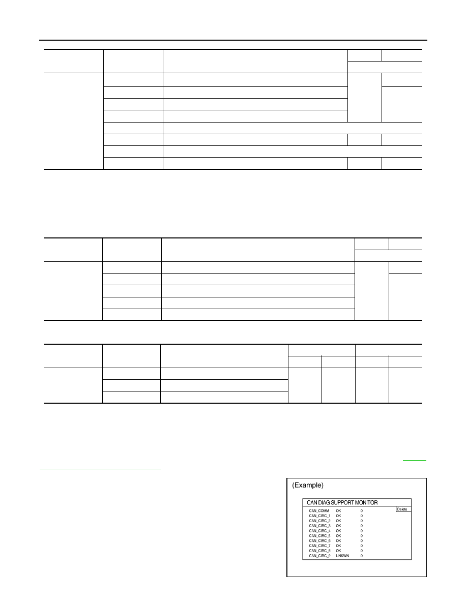
ITEM
CAN DIAG SUP-
PORT MNTR
Description
Normal
Error
PRSNT
ABS
INITIAL DIAG
Status of CAN controller
OK
NG
Caution
TRANSMIT DIAG
Signal transmission status
UNKWN
ECM
Signal receiving status from the ECM
TCM
Signal receiving status from the TCM
METER/M&A
Not used even though indicated
STRG
Signal receiving status from the steering angle sensor
OK
UNKWN
ICC
Not used even though indicated
AWD/4WD
Signal receiving status from the AWD control unit
OK
UNKWN
ITEM
CAN DIAG SUP-
PORT MNTR
Description
Normal
Error
PRSNT
ADP
INITIAL DIAG
Status of CAN controller
OK
NG
TRANSMIT DIAG
Signal transmission status
UNKWN
BCM/SEC
Signal receiving status from the BCM
METER/M&A
Signal receiving status from the unified meter and A/C amp.
TCM
Signal receiving status from the TCM
ITEM
CAN DIAG SUP-
PORT MNTR
Description
Normal
Error
PRSNT
PAST
PRSNT
PAST
IPDM-E
TRANSMIT DIAG
Signal transmission status
OK
OK
or
1 – 39
*
UNKWN
0
ECM
Signal receiving status from the ECM
BCM/SEC
Signal receiving status from the BCM
PKIB6080E
TROUBLE DIAGNOSIS
LAN-43
< SERVICE INFORMATION >
[CAN]
C
D
E
F
G
H
I
J
L
M
A
B
LAN
N
O
P
*: The error counter stops counting when it reaches “50” and holds “50” until it is deleted.
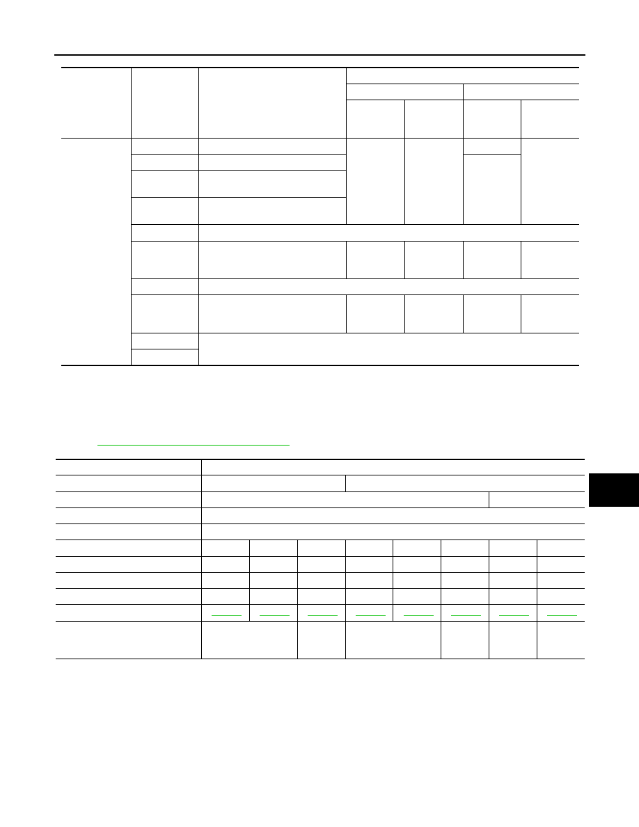
CAN System Specification Chart
INFOID:0000000001328635
Determine CAN system type from the following specification chart. Then choose the correct diagnosis sheet.
NOTE:
Refer to
LAN-14, "Trouble Diagnosis Procedure"
for how to use CAN system specification chart.
VEHICLE EQUIPMENT IDENTIFICATION INFORMATION
NOTE:
Unit name
Diagnosis item
Description
Indicated items on CAN DIAG SUPPORT MONITOR
Normal
Error
Result indi-
cated
Error
counter
(Reference)
Result indi-
cated
Error
counter
(Reference)
Display control
unit
CAN_COMM
Status of CAN controller
OK
0
or
1 – 50*
NG
1 – 50*
CAN_CIRC_1
Signal transmission status
UNKWN
CAN_CIRC_2
Signal receiving status from the
BCM
CAN_CIRC_3
Signal receiving status from the
ECM
CAN_CIRC_4
Not used even though indicated
CAN_CIRC_5
Signal receiving status from the uni-
fied meter and A/C amp.
OK
0
or
1 – 50*
UNKWN
1 – 50*
CAN_CIRC_6
Not used even though indicated
CAN_CIRC_7
Signal receiving status from the
IPDM E/R
OK
0
or
1 – 50*
UNKWN
1 – 50*
CAN_CIRC_8
Not used even though indicated
CAN_CIRC_9
Body type
Wagon
Axle
2WD
AWD
Engine
VQ35DE
VK45DE
Transmission
A/T
Brake control
VDC
ICC system
×
×
×
Intelligent Key system
×
×
×
×
×
×
Lane departure warning system
×
×
×
CAN system type
1
2
3
4
5
6
7
8
Diagnosis sheet
CAN communication signal chart
“TYPE 1/TYPE 2”
“TYPE 3”
“TYPE 4/TYPE 5/
TYPE 7”
“TYPE 6/
TYPE 8”
“TYPE 4/
TYPE 5/
TYPE 7”
“TYPE 6/
TYPE 8”
LAN-44
< SERVICE INFORMATION >
[CAN]
TROUBLE DIAGNOSIS
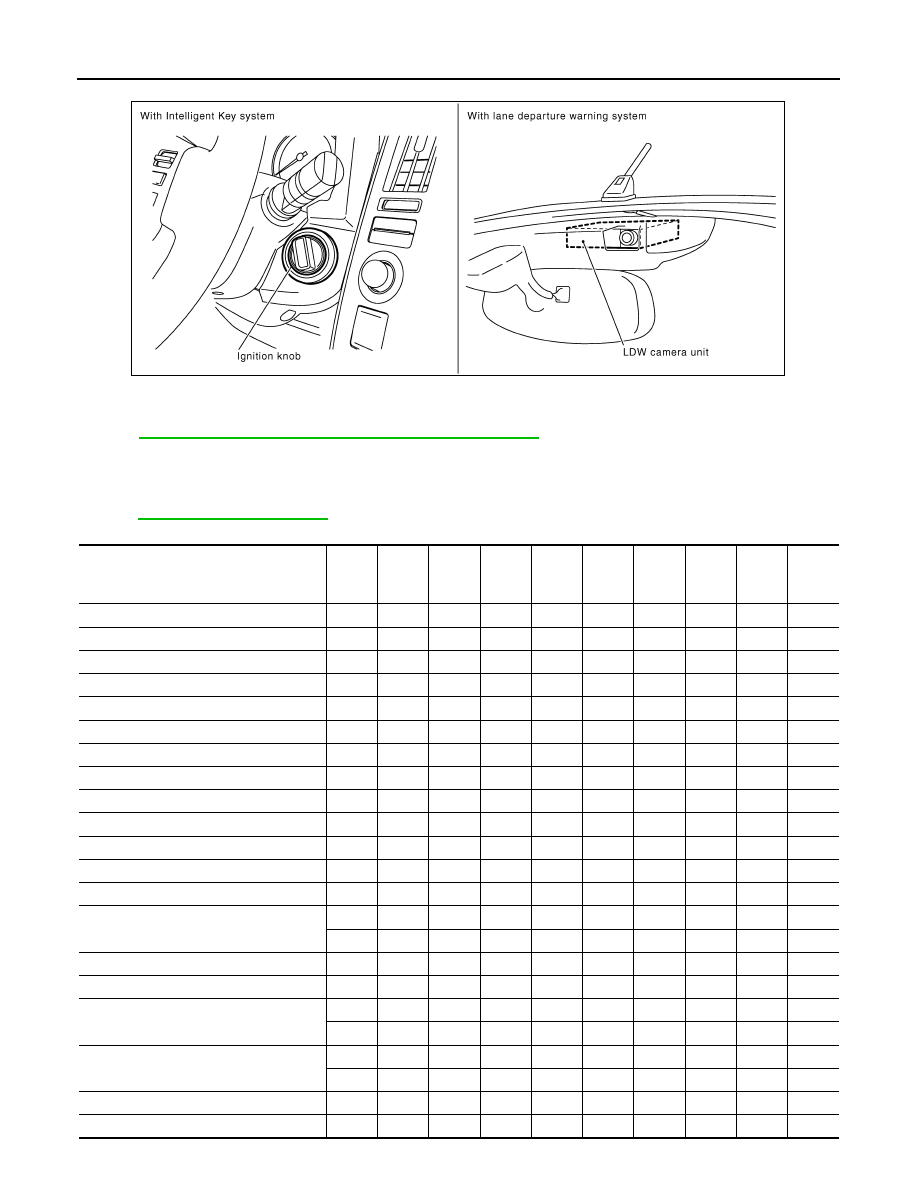
Check CAN system type from the vehicle shape and equipment.
CAN Communication Signal Chart
INFOID:0000000001328636
LAN-13, "How to Use CAN Communication Signal Chart"
for how to use CAN communication signal
chart.
TYPE 1/TYPE 2
NOTE:
Refer to
for the abbreviations of the connecting units.
T: Transmit
R: Receive
PKID0615E
Signal name/Connecting unit
ECM
DIS
P
TCM
BCM
I-KEY
STRG
M&A
ABS
ADP
IPDM
-E
A/C compressor feedback signal
T
R
A/C compressor request signal
T
R
Accelerator pedal position signal
T
R
R
ASCD CRUISE lamp signal
T
R
ASCD OD cancel request signal
T
R
ASCD operation signal
T
R
ASCD SET lamp signal
T
R
Battery voltage signal
T
R
Closed throttle position signal
T
R
Cooling fan speed request signal
T
R
Engine coolant temperature signal
T
R
Engine speed signal
T
R
R
R
R
Engine status signal
T
R
Fuel consumption monitor signal
T
R
R
T
Malfunctioning indicator lamp signal
T
R
Wide open throttle position signal
T
R
A/C switch/indicator signal
T
R
R
T
System setting signal
T
R
R
R
T
T
A/T CHECK indicator lamp signal
T
R
A/T self-diagnosis signal
R
T
Нет комментариевНе стесняйтесь поделиться с нами вашим ценным мнением.
Текст