Infiniti FX35 / FX45. Manual — part 808

PARKING, LICENSE PLATE AND TAIL LAMPS
LT-127
< SERVICE INFORMATION >
C
D
E
F
G
H
I
J
L
M
A
B
LT
N
O
P
Terminal and Reference Value for IPDM E/R
INFOID:0000000001328389
Terminal
No.
Wire
color
Signal name
Measuring condition
Reference value
Ignition
switch
Operation or condition
2
GY
Combination
switch input 5
ON
Lighting, turn, wip-
er switch
(Wiper intermittent
dial position 4)
OFF
Approx. 0 V
Lighting switch 1ST
Approx. 1.0 V
11
LG
Ignition switch
(ACC)
ACC
—
Battery voltage
33
G
Combination
switch output 4
ON
Lighting, turn, wip-
er switch
(Wiper intermittent
dial position 4)
OFF
Approx. 7.2 V
Lighting switch 1ST
(The same result with
lighting switch 2ND)
Approx. 1.2 V
38
W/L
Ignition switch
(ON)
ON
—
Battery voltage
39
L
CAN
−
H
—
—
—
40
P
CAN
−
L
—
—
—
42
L/R
Battery power
supply
OFF
—
Battery voltage
49
B
Ground
ON
—
Approx. 0 V
52
B
Ground
ON
—
Approx. 0 V
55
G
Battery power
supply
OFF
—
Battery voltage
PKIB4959J
PKIB4960J
PKIB4958J
Terminal
No.
Wire
color
Signal name
Measuring condition
Reference value
Ignition
switch
Operation or condition
22
R
Parking, license plate,
side marker, and tail
lamps
ON
Lighting switch
1ST position
OFF
Approx. 0 V
ON
Battery voltage
38
B
Ground
ON
—
Approx. 0 V
48
L
CAN
−
H
—
—
—

LT-128
< SERVICE INFORMATION >
PARKING, LICENSE PLATE AND TAIL LAMPS
Terminal and Reference Value for Rear Combination Lamp Control Unit
INFOID:0000000001328390
LT-86, "Terminal and Reference Value for Rear Combination Lamp Control Unit"
How to Proceed with Trouble Diagnosis
INFOID:0000000001328391
1.
Confirm the symptom or customer complaint.
2.
Understand operation description and function description. Refer to
3.
Perform Preliminary Check. Refer to
.
4.
Check symptom and repair or replace the cause of malfunction.
5.
Do parking, license plate, side marker and tail lamps operate normally? If YES, GO TO 6. If NO, GO TO 4.
6.
INSPECTION END
Preliminary Check
INFOID:0000000001328392
CHECK POWER SUPPLY AND GROUND CIRCUIT
1.
CHECK FUSES
Check for blown fuses.
Refer to
LT-122, "Wiring Diagram - TAIL/L -"
OK or NG
OK
>> GO TO 2.
NG
>> If fuse is blown, be sure to eliminate cause of malfunction before installing new fuse. Refer to
2.
CHECK POWER SUPPLY CIRCUIT
49
R
CAN
−
L
—
—
—
60
B
Ground
ON
—
Approx. 0 V
Terminal
No.
Wire
color
Signal name
Measuring condition
Reference value
Ignition
switch
Operation or condition
Unit
Power source
Fuse and fusible link No.
BCM
Battery
M
22
Ignition switch ON or START position
1
Ignition switch ACC or ON position
6
IPDM E/R
Battery
71
Rear combination lamp control unit
Battery
20
PARKING, LICENSE PLATE AND TAIL LAMPS
LT-129
< SERVICE INFORMATION >
C
D
E
F
G
H
I
J
L
M
A
B
LT
N
O
P
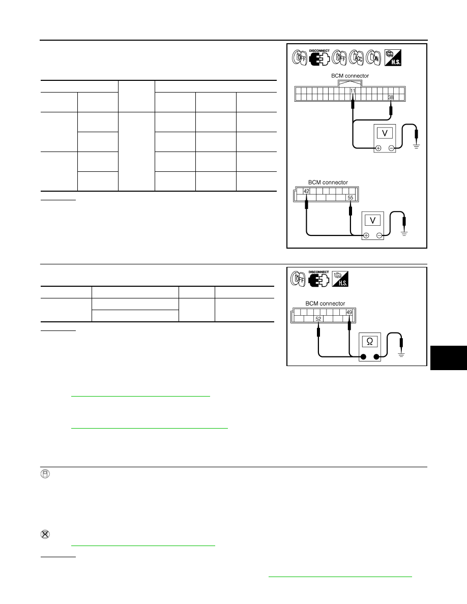
1.
Turn ignition switch OFF.
2.
Disconnect BCM connector.
3.
Check voltage between BCM harness connector and ground.
OK or NG
OK
>> GO TO 3.
NG
>> Repair harness or connector.
3.
CHECK GROUND CIRCUIT
Check continuity between BCM harness connector and ground.
OK or NG
OK
>> INSPECTION END
NG
>> Repair harness or connector.
CONSULT-III Functions (BCM)
INFOID:0000000001328393
LT-16, "CONSULT-III Functions (BCM)"
CONSULT-III Functions (IPDM E/R)
INFOID:0000000001328394
LT-17, "CONSULT-III Functions (IPDM E/R)"
Parking, License Plate and Side Marker Lamps Do Not Illuminate
INFOID:0000000001328395
1.
CHECK COMBINATION SWITCH INPUT SIGNAL
CONSULT-III DATA MONITOR
1.
Select “LIGHT SW 1ST” of BCM data monitor item.
2.
With operating the lighting switch, check the monitor status.
CHECK COMBINATION SWITCH
LT-104, "Combination Switch Inspection"
OK or NG
OK
>> GO TO 2.
NG
>> Check combination switch (lighting switch). Refer to
LT-104, "Combination Switch Inspection"
.
(+)
(-)
Ignition switch position
BCM con-
nector
Terminal
OFF
ACC
ON
M3
11
Ground
Approx. 0 V
Battery volt-
age
Battery volt-
age
38
Approx. 0 V
Approx. 0 V
Battery volt-
age
M4
42
Battery volt-
age
Battery volt-
age
Battery volt-
age
55
Battery volt-
age
Battery volt-
age
Battery volt-
age
PKIA5204E
BCM connector
Terminal
Continuity
M4
49
Ground
Yes
52
SKIA5294E
When lighting switch is 1ST
position
: LIGHT SW 1ST ON
LT-130
< SERVICE INFORMATION >
PARKING, LICENSE PLATE AND TAIL LAMPS
2.
ACTIVE TEST
CONSULT-III ACTIVE TEST
1.
Select “TAIL LAMP” of IPDM E/R active test item.
2.
With operating the test item, check the parking, license plate, side marker and tail lamps operation.
IPDM E/R AUTO ACTIVE TEST
1.
Start auto active test. Refer to
2.
Check that the parking, license plate, side marker and tail lamps operation.
OK or NG
OK
>> GO TO 3.
NG
>> GO TO 4.
3.
CHECK IPDM E/R
1.
Select “TAIL&CLR REQ” of IPDM E/R data monitor item.
2.
With operating the lighting switch, check the monitor status.
OK or NG
OK
>> Replace IPDM E/R. Refer to
PG-24, "Removal and Installation of IPDM E/R"
NG
>> Replace BCM. Refer to
BCS-13, "Removal and Installation of BCM"
.
4.
CHECK IPDM E/R
CONSULT-III ACTIVE TEST
1.
Turn ignition switch OFF.
2.
Disconnect front side marker lamp, parking lamp, license plate lamp and rear combination lamp connec-
tors.
3.
Select “TAIL LAMP” of IPDM E/R active test item.
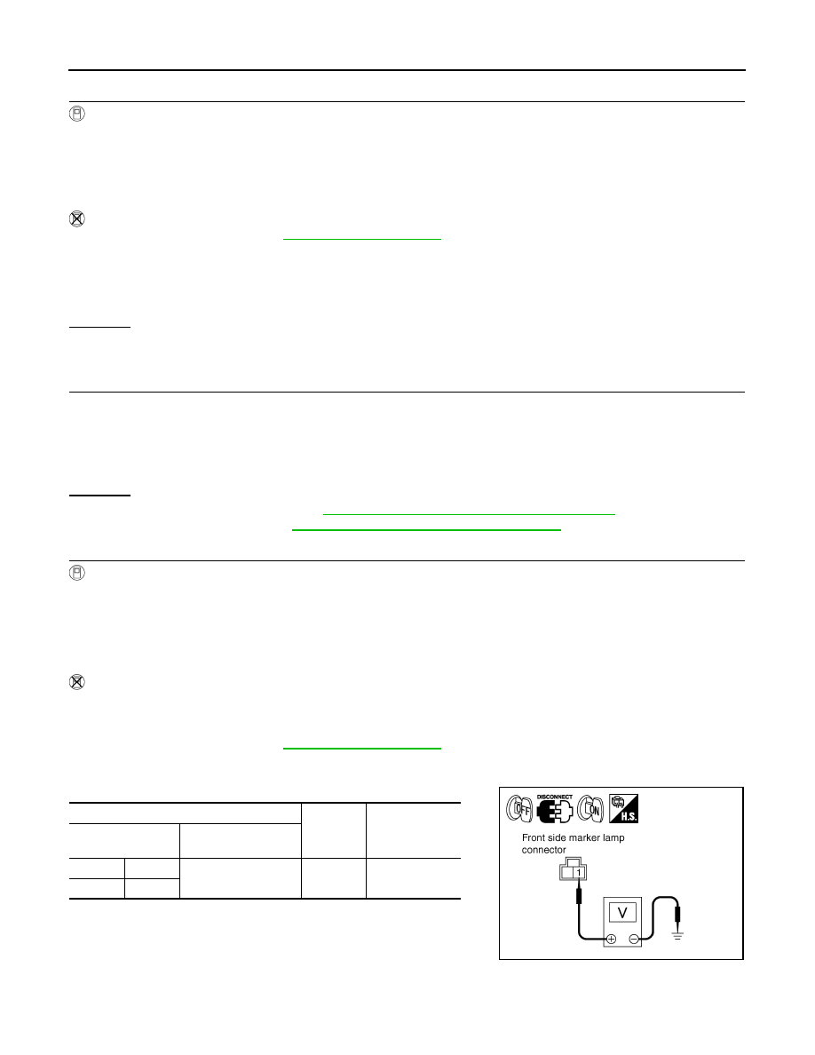
4.
With operating the test item, check voltage between front side marker lamp, parking lamp, license plate
lamp and rear combination lamp harness connector and ground.
IPDM E/R AUTO ACTIVE TEST
1.
Turn ignition switch OFF.
2.
Disconnect front side marker lamp, parking lamp, license plate lamp and rear combination lamp connec-
tor.
3.
Start auto active test. Refer to
4.
With operating the test item, check voltage between front side marker lamp, parking lamp, license plate
lamp and rear combination lamp harness connector and ground.
Parking, license plate, side marker and tail lamps
should operate.
Parking, license plate, side marker and tail lamps
should operate.
When lighting switch is 1ST
position
: TAIL&CLR REQ ON
(+)
(-)
Voltage
Front side marker
lamp connector
Terminal
RH
E22
1
Ground Battery
voltage
LH
E42
PKIA5236E
Нет комментариевНе стесняйтесь поделиться с нами вашим ценным мнением.
Текст