Infiniti FX35 / FX45. Manual — part 482
TROUBLE DIAGNOSIS
EC-689
< SERVICE INFORMATION >
[VK45DE]
C
D
E
F
G
H
I
J
K
L
M
A
EC
N
P
O
13
Y
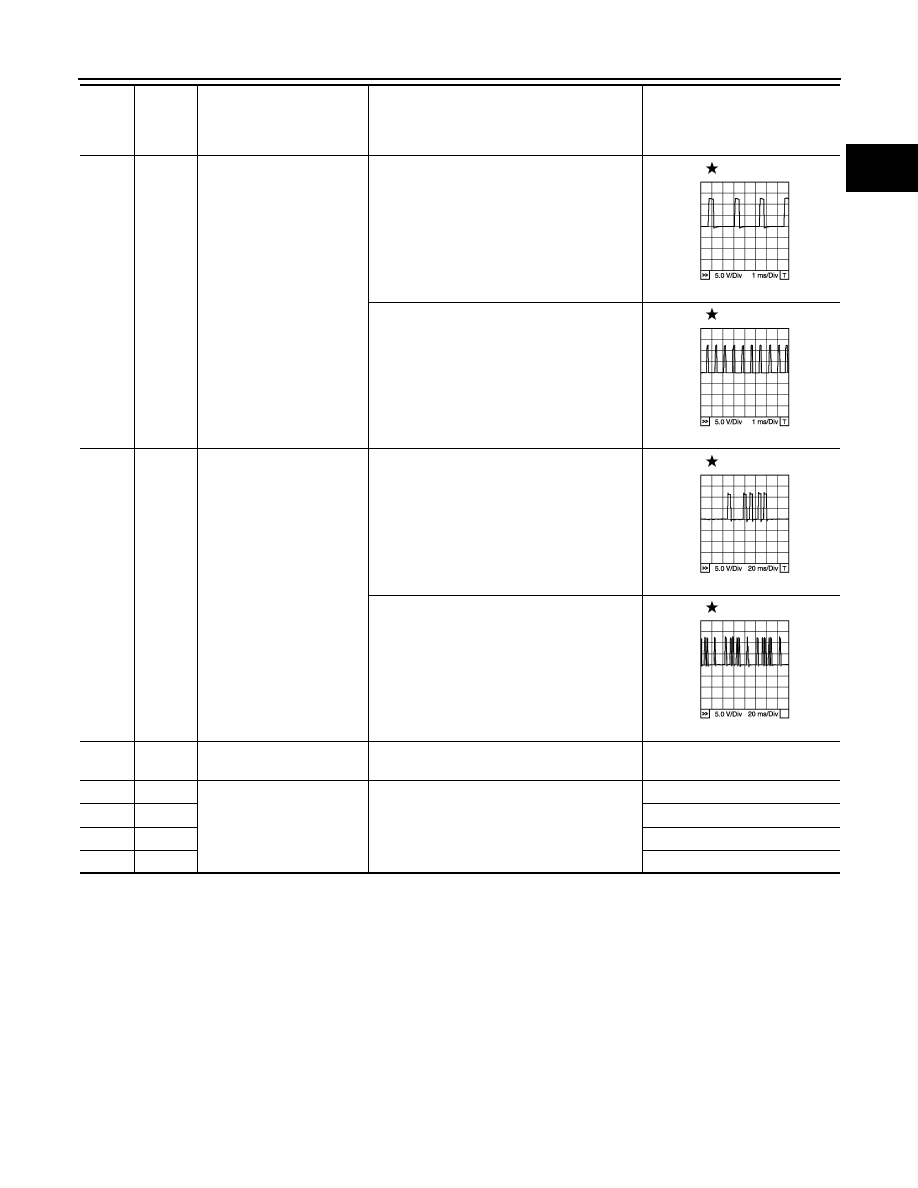
Crankshaft position sensor
(POS)
[Engine is running]
• Warm-up condition
• Idle speed
NOTE:
The pulse cycle changes depending on rpm
at idle
1.0 - 2.0V
[Engine is running]
• Engine speed: 2,000 rpm
1.0 - 2.0V
14
W
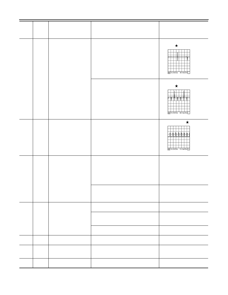
Camshaft position sensor
(PHASE)
[Engine is running]
• Warm-up condition
• Idle speed
NOTE:
The pulse cycle changes depending on rpm
at idle
1.0 - 4.0V
[Engine is running]
• Engine speed: 2,000 rpm
1.0 - 4.0V
15
W
Knock sensor (Bank 1)
[Engine is running]
• Idle speed
Approximately 2.5V
16
R
A/F sensor 1 (Bank 1)
[Engine is running]
• Warm-up condition
• Idle speed
Approximately 3.1V
35
G
Approximately 2.6V
56
B
Approximately 2.3V
75
OR
Approximately 2.3V
TER-
MI-
NAL
NO.
WIRE
COLOR
ITEM
CONDITION
DATA (DC Voltage)
PBIB1041E
PBIB1042E
PBIB1039E
PBIB1040E
EC-690
< SERVICE INFORMATION >
[VK45DE]
TROUBLE DIAGNOSIS
21
22
23
40
41
42
44
63
W
R
P
PU
BR
B
OR
G
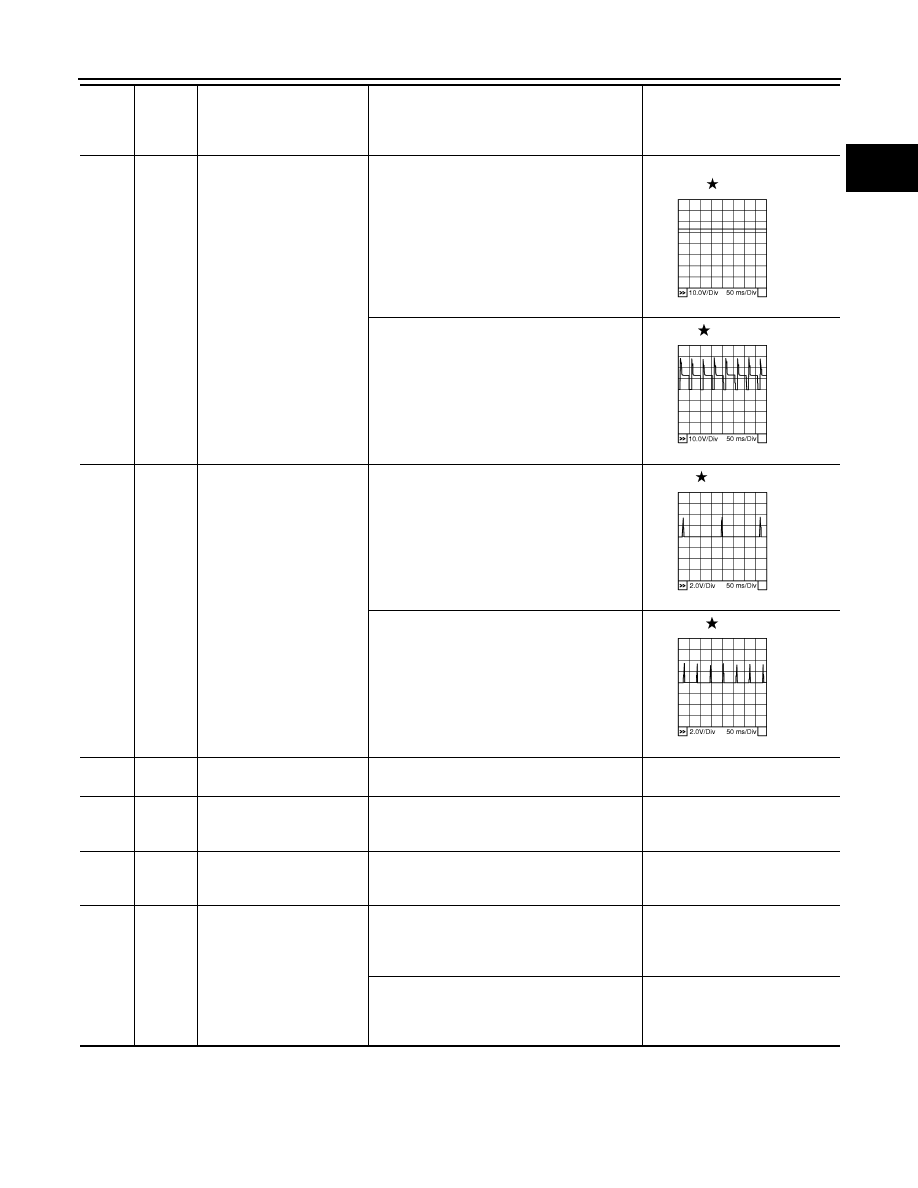
Fuel injector No. 5
Fuel injector No. 3
Fuel injector No. 1
Fuel injector No. 6
Fuel injector No. 4
Fuel injector No. 2
Fuel injector No. 7
Fuel injector No. 8
[Engine is running]
• Warm-up condition
• Idle speed
NOTE:
The pulse cycle changes depending on rpm
at idle
BATTERY VOLTAGE
(11 - 14V)
[Engine is running]
• Warm-up condition
• Engine speed: 2,000 rpm
BATTERY VOLTAGE
(11 - 14V)
24
P
A/F sensor 1 heater
(Bank 2)
[Engine is running]
• Warm-up condition
• Idle speed
Approximately 5V
25
P
Heated oxygen sensor 2
heater (Bank 2)
[Engine is running]
• Engine speed: Below 3,600 rpm after the fol-
lowing conditions are met
- Engine: After warming up
- Keeping the engine speed between 3,500
and 4,000 rpm for 1 minute and at idle for 1
minute under no load
0 - 1.0V
[Ignition switch: ON]
• Engine stopped
[Engine is running]
• Engine speed: Above 3,600 rpm
BATTERY VOLTAGE
(11 - 14V)
29
GY
VIAS control solenoid valve
[Engine is running]
• Selector lever: P or N
0 - 1.0V
[Engine is running]
• Selector lever: D
• Engine speed: Below 5,000 rpm
BATTERY VOLTAGE
(11 - 14V)
[Engine is running]
• Engine speed: Above 5,000 rpm
0 - 1.0V
32
OR
EVAP control system pres-
sure sensor
[Ignition switch: ON]
Approximately 1.8 - 4.8V
34
Y
Intake air temperature sen-
sor
[Engine is running]
Approximately 0 - 4.8V
Output voltage varies with intake
air temperature.
36
W
Knock sensor (Bank 2)
[Engine is running]
• Idle speed
Approximately 2.5V
TER-
MI-
NAL
NO.
WIRE
COLOR
ITEM
CONDITION
DATA (DC Voltage)
PBIB0042E
PBIB0043E
PBIB1584E
TROUBLE DIAGNOSIS
EC-691
< SERVICE INFORMATION >
[VK45DE]
C
D
E
F
G
H
I
J
K
L
M
A
EC
N
P
O
45
W
EVAP canister purge volume
control solenoid valve
[Engine is running]
• Idle speed
BATTERY VOLTAGE
(11 - 14V)
[Engine is running]
• Engine speed: About 2,000 rpm (More than
100 seconds after starting engine)
11 - 14V
46
60
61
62
65
79
80
81
BR
SB
L
Y
P
LG
GY
G
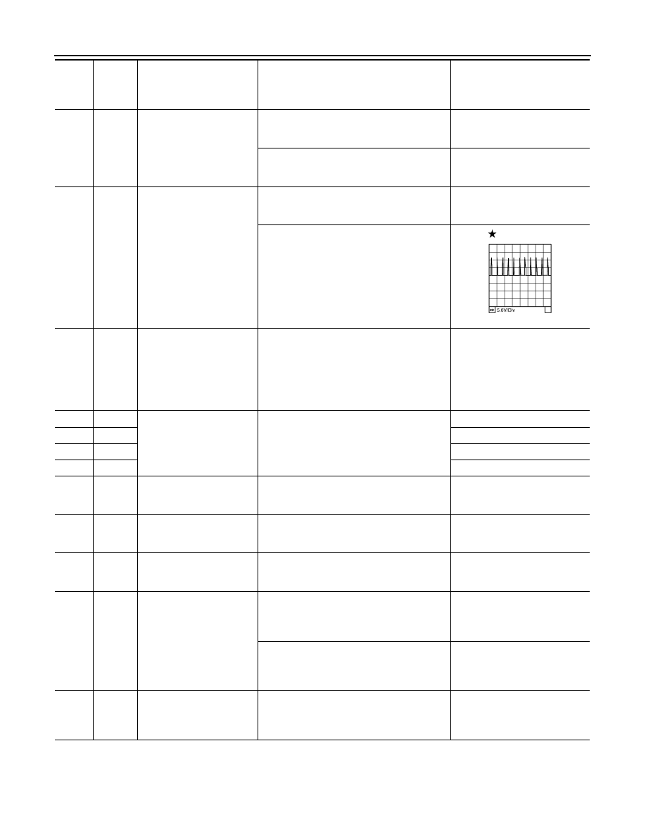
Ignition signal No. 7
Ignition signal No. 5
Ignition signal No. 3
Ignition signal No. 1
Ignition signal No. 8
Ignition signal No. 6
Ignition signal No. 4
Ignition signal No. 2
[Engine is running]
• Warm-up condition
• Idle speed
NOTE:
The pulse cycle changes depending on rpm
at idle
0 - 0.2V
[Engine is running]
• Warm-up condition
• Engine speed: 2,000 rpm
0.1 - 0.4V
47
L
Sensor power supply (Throt-
tle position sensor)
[Ignition switch: ON]
Approximately 5V
48
L
Sensor power supply
(EVAP control system pres-
sure sensor)
[Ignition switch: ON]
Approximately 5V
49
PU
Sensor power supply
(Refrigerant pressure sen-
sor)
[Ignition switch: ON]
Approximately 5V
50
W
Throttle position sensor 1
[Ignition switch: ON]
• Engine stopped
• Selector lever: D
• Accelerator pedal: Fully released
More than 0.36V
[Ignition switch: ON]
• Engine stopped
• Selector lever: D
• Accelerator pedal: Fully depressed
Less than 4.75V
TER-
MI-
NAL
NO.
WIRE
COLOR
ITEM
CONDITION
DATA (DC Voltage)
PBIB0050E
PBIB0051E
PBIB0044E
PBIB0045E
EC-692
< SERVICE INFORMATION >
[VK45DE]
TROUBLE DIAGNOSIS
51
L/W
Mass air flow sensor
[Engine is running]
• Warm-up condition
• Idle speed
1.0 - 1.3V
[Engine is running]
• Warm-up condition
• Engine speed: 2,500 rpm
1.6 - 2.0V
53
R/L
Intake valve timing control
position sensor (Bank 2)
[Engine is running]
• Warm-up condition
• Idle speed
0 - 1.0V
[Engine is running]
• Engine speed: 2,000 rpm
0 - 1.0V
55
W/R
Heated oxygen sensor 2
(Bank 1)
[Engine is running]
• Revving engine from idle to 3,000 rpm quick-
ly after the following conditions are met
- Engine: After warming up
- After keeping the engine speed between
3,500 and 4,000 rpm for 1 minute and at idle
for 1 minute under no load
0 - Approximately 1.0V
57
G
A/F sensor 1 (Bank 2)
[Engine is running]
• Warm-up condition
• Idle speed
Approximately 2.6V
58
L
Approximately 2.3V
76
R
Approximately 3.1V
77
OR
Approximately 2.3V
66
B
Sensor ground
(Throttle position sensor)
[Engine is running]
• Warm-up condition
• Idle speed
Approximately 0V
67
B/W
Sensor ground
[Engine is running]
• Warm-up condition
• Idle speed
Approximately 0V
68
SB
Sensor power supply
(Power steering pressure
sensor)
[Ignition switch: ON]
Approximately 5V
69
R
Throttle position sensor 2
[Ignition switch: ON]
• Engine stopped
• Selector lever: D
• Accelerator pedal: Fully released
Less than 4.75V
[Ignition switch: ON]
• Engine stopped
• Selector lever: D
• Accelerator pedal: Fully depressed
More than 0.36V
70
L/R
Refrigerant pressure sensor
[Engine is running]
• Warm-up condition
• Both A/C switch and blower fan motor
switch: ON (Compressor operates)
1.0 - 4.0V
TER-
MI-
NAL
NO.
WIRE
COLOR
ITEM
CONDITION
DATA (DC Voltage)
PBIB2046E
Нет комментариевНе стесняйтесь поделиться с нами вашим ценным мнением.
Текст