Infiniti FX35 / FX45. Manual — part 460
INDEX FOR DTC
EC-601
< SERVICE INFORMATION >
[VK45DE]
C
D
E
F
G
H
I
J
K
L
M
A
EC
N
P
O
HO2S2 (B1)
P0137
0137
HO2S2 (B1)
P0138
0138
HO2S2 (B1)
P0139
0139
HO2S2 (B2)
P0157
0157
HO2S2 (B2)
P0158
0158
HO2S2 (B2)
P0159
0159
HO2S2 HTR (B1)
P0037
0037
HO2S2 HTR (B1)
P0038
0038
HO2S2 HTR (B2)
P0057
0057
HO2S2 HTR (B2)
P0058
0058
I/C SOLENOID/CIRC
P1752
1752
IAT SEN/CIRCUIT-B1
P0112
0112
IAT SEN/CIRCUIT-B1
P0113
0113
IAT SENSOR-B1
P0127
0127
ICC COMMAND VALUE*
6
P1568
1568
ID DISCORD, IMM-ECM
P1611
1611
IN PULY SPEED
P1715
1715
INT/V TIM CONT-B1
P0011
0011
INT/V TIM CONT-B2
P0021
0021
INT/V TIM V/CIR-B1
P0075
0075
INT/V TIM V/CIR-B2
P0081
0081
INTK TIM S/CIRC-B1
P1140
1140
INTK TIM S/CIRC-B2
P1145
1145
ISC SYSTEM
P0506
0506
ISC SYSTEM
P0507
0507
KNOCK SEN/CIRC-B1
P0327
0327
KNOCK SEN/CIRC-B1
P0328
0328
KNOCK SEN/CIRC-B2
P0332
0332
KNOCK SEN/CIRC-B2
P0333
0333
L/PRESS SOL/CIRC
P0745
0745
LC/B SOLENOID FNCT
P1774
1774
LC/B SOLENOID/CIRC
P1610
1610
LOCK MODE
P1772
1772
MAF SEN/CIRCUIT-B1
P0101
0101
MAF SEN/CIRCUIT-B1
P0102
0102
MAF SEN/CIRCUIT-B1
P0103
0103
MULTI CYL MISFIRE
P0300
0300
NATS MALFUNCTION
P1610 - P1615
1610 - 1615
NO DTC IS DETECTED.
FURTHER TESTING
MAY BE REQUIRED.
P0000
0000
—
P-N POS SW/CIRCUIT
P0850
0850
PNP SW/CIRC
P0705
0705
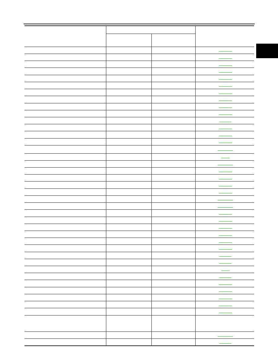
Items
(CONSULT-III screen terms)
DTC*
1
Reference page
CONSULT-III
GST*
2
ECM*
3

EC-602
< SERVICE INFORMATION >
[VK45DE]
INDEX FOR DTC
*1: 1st trip DTC No. is the same as DTC No.
*2: This number is prescribed by SAE J2012.
*3: In Diagnostic Test Mode II (Self-diagnostic results), this number is controlled by NISSAN.
*4: The troubleshooting for this DTC needs CONSULT-III.
*5: When the fail-safe operations for both self-diagnoses occur, the MIL illuminates.
*6: Models with ICC.
PURG VOLUME CONT/V
P0443
0443
PURG VOLUME CONT/V
P0444
0444
PURG VOLUME CONT/V
P0445
0445
PW ST P SEN/CIRC
P0550
0550
SENSOR POWER/CIRC
P0643
0643
TCC SOLENOID/CIRC
P0740
0740
TCM
P0700
0700
TCS C/U FUNCTN
P1211
1211
TCS/CIRC
P1212
1212
THERMSTAT FNCTN
P0128
0128
TP SEN 1/CIRC-B1
P0222
0222
TP SEN 1/CIRC-B1
P0223
0223
TP SEN 2/CIRC-B1
P0122
0122
TP SEN 2/CIRC-B1
P0123
0123
TP SENSOR-B1
P2135
2135
TURBINE SENSOR
P0717
0717
TW CATALYST SYS-B1
P0420
0420
TW CATALYST SYS-B2
P0430
0430
VEH SPD SEN/CIR AT*
5
P0720
0720
VEH SPEED SEN/CIRC*
5
P0500
0500
VENT CONTROL VALVE
P0447
0447
VENT CONTROL VALVE
P0448
0448
VIAS S/V-1
P1800
1800
Items
(CONSULT-III screen terms)
DTC*
1
Reference page
CONSULT-III
GST*
2
ECM*
3
PRECAUTIONS
EC-603
< SERVICE INFORMATION >
[VK45DE]
C
D
E
F
G
H
I
J
K
L
M
A
EC
N
P
O
PRECAUTIONS
Precaution for Supplemental Restraint System (SRS) "AIR BAG" and "SEAT BELT
PRE-TENSIONER"
INFOID:0000000001612919
The Supplemental Restraint System such as “AIR BAG” and “SEAT BELT PRE-TENSIONER”, used along
with a front seat belt, helps to reduce the risk or severity of injury to the driver and front passenger for certain
types of collision. This system includes seat belt switch inputs and dual stage front air bag modules. The SRS
system uses the seat belt switches to determine the front air bag deployment, and may only deploy one front
air bag, depending on the severity of a collision and whether the front occupants are belted or unbelted.
Information necessary to service the system safely is included in the “SUPPLEMENTAL RESTRAINT SYS-
TEM” and “SEAT BELTS” of this Service Manual.
WARNING:
• To avoid rendering the SRS inoperative, which could increase the risk of personal injury or death in
the event of a collision which would result in air bag inflation, all maintenance must be performed by
an authorized NISSAN/INFINITI dealer.
• Improper maintenance, including incorrect removal and installation of the SRS, can lead to personal
injury caused by unintentional activation of the system. For removal of Spiral Cable and Air Bag
Module, see the “SUPPLEMENTAL RESTRAINT SYSTEM”.
• Do not use electrical test equipment on any circuit related to the SRS unless instructed to in this
Service Manual. SRS wiring harnesses can be identified by yellow and/or orange harnesses or har-
ness connectors.
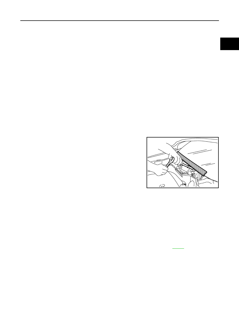
Precaution for Procedure without Cowl Top Cover
INFOID:0000000001612941
When performing the procedure after removing cowl top cover, cover
the lower end of windshield with urethane, etc.
On Board Diagnosis (OBD) System of Engine and A/T
INFOID:0000000001326487
The ECM has an on board diagnostic system. It will light up the malfunction indicator lamp (MIL) to warn the
driver of a malfunction causing emission deterioration.
CAUTION:
• Be sure to turn the ignition switch OFF and disconnect the negative battery cable before any repair
or inspection work. The open/short circuit of related switches, sensors, solenoid valves, etc. will
cause the MIL to light up.
• Be sure to connect and lock the connectors securely after work. A loose (unlocked) connector will
cause the MIL to light up due to the open circuit. (Be sure the connector is free from water, grease,
dirt, bent terminals, etc.)
• Certain systems and components, especially those related to OBD, may use a new style slide-lock-
ing type harness connector. For description and how to disconnect, refer to
.
• Be sure to route and secure the harnesses properly after work. The interference of the harness with
a bracket, etc. may cause the MIL to light up due to the short circuit.
• Be sure to connect rubber tubes properly after work. A misconnected or disconnected rubber tube
may cause the MIL to light up due to the malfunction of the EVAP system or fuel injection system,
etc.
• Be sure to erase the unnecessary malfunction information (repairs completed) from the ECM and
TCM (Transmission control module) before returning the vehicle to the customer.
PIIB3706J
EC-604
< SERVICE INFORMATION >
[VK45DE]
PRECAUTIONS
Precaution
INFOID:0000000001326488
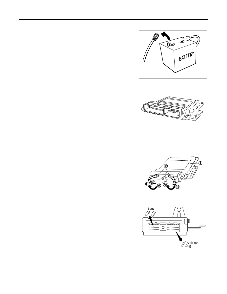
• Always use a 12 volt battery as power source.
• Do not attempt to disconnect battery cables while engine is
running.
• Before connecting or disconnecting the ECM harness con-
nector, turn ignition switch OFF and disconnect negative bat-
tery cable. Failure to do so may damage the ECM because
battery voltage is applied to ECM even if ignition switch is
turned OFF.
• Before removing parts, turn ignition switch OFF and then dis-
connect battery ground cable.
• Do not disassemble ECM.
• If a battery cable is disconnected, the memory will return to
the ECM value.
The ECM will now start to self-control at its initial value.
Engine operation can vary slightly when the terminal is dis-
connected. However, this is not an indication of a malfunc-
tion. Do not replace parts because of a slight variation.
• If the battery is disconnected, the following emission-related
diagnostic information will be lost within 24 hours.
- Diagnostic trouble codes
- 1st trip diagnostic trouble codes
- Freeze frame data
- 1st trip freeze frame data
- System readiness test (SRT) codes
- Test values
• When connecting ECM harness connector, fasten (B) it
securely with a lever (2) as far as it will go as shown in the fig-
ure.
- ECM (1)
- Loosen (A)
• When connecting or disconnecting pin connectors into or
from ECM, take care not to damage pin terminals (bend or
break).
Make sure that there are not any bends or breaks on ECM pin
terminal, when connecting pin connectors.
• Securely connect ECM harness connectors.
A poor connection can cause an extremely high (surge) volt-
age to develop in coil and condenser, thus resulting in dam-
age to ICs.
• Keep engine control system harness at least 10 cm (4 in) away
from adjacent harness, to prevent engine control system mal-
functions due to receiving external noise, degraded operation
of ICs, etc.
• Keep engine control system parts and harness dry.
SEF289H
PBIB1164E
PBIB3223E
PBIB0090E
Нет комментариевНе стесняйтесь поделиться с нами вашим ценным мнением.
Текст