Infiniti FX35 / FX45. Manual — part 686
CYLINDER BLOCK
EM-261
< SERVICE INFORMATION >
[VK45DE]
C
D
E
F
G
H
I
J
K
L
M
A
EM
N
P
O
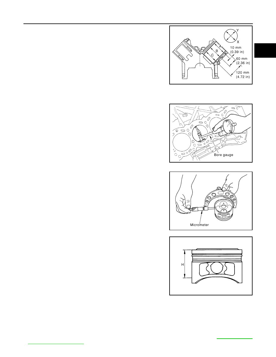
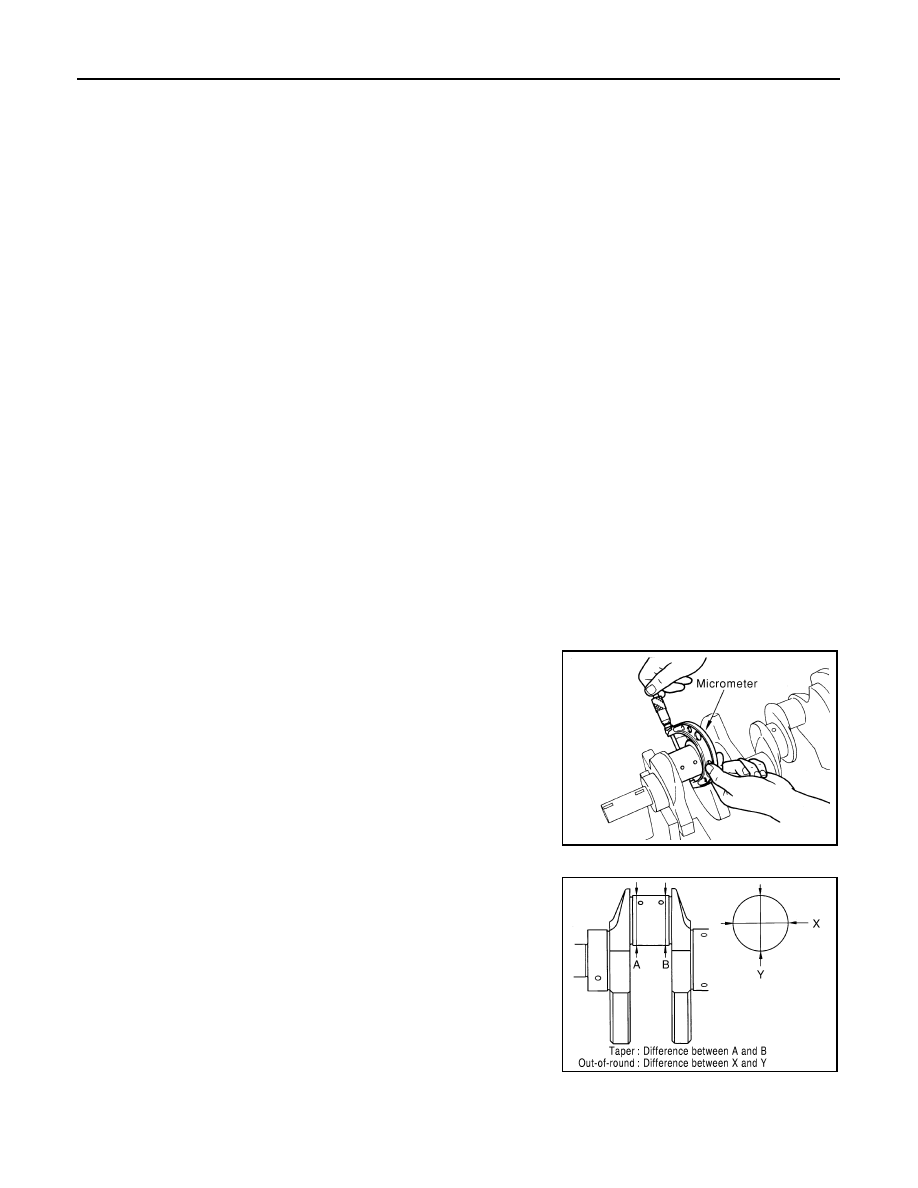
• Using bore gauge, measure cylinder bore for wear, out-of-round
and taper at six different points on each cylinder. (“X” and “Y” direc-
tions at “A”, “B” and “C”) (“Y” is in longitudinal direction of engine)
• If the measured value exceeds the limit, or if there are scratches
and/or seizure on the cylinder inner wall, hone or re-bore the inner
wall.
• Oversize piston is provided. When using oversize piston, re-bore
cylinder so that the clearance of the piston-to-cylinder bore satis-
fies the standard.
CAUTION:
When using oversize piston, use oversize pistons for all cylin-
ders with oversize piston rings.
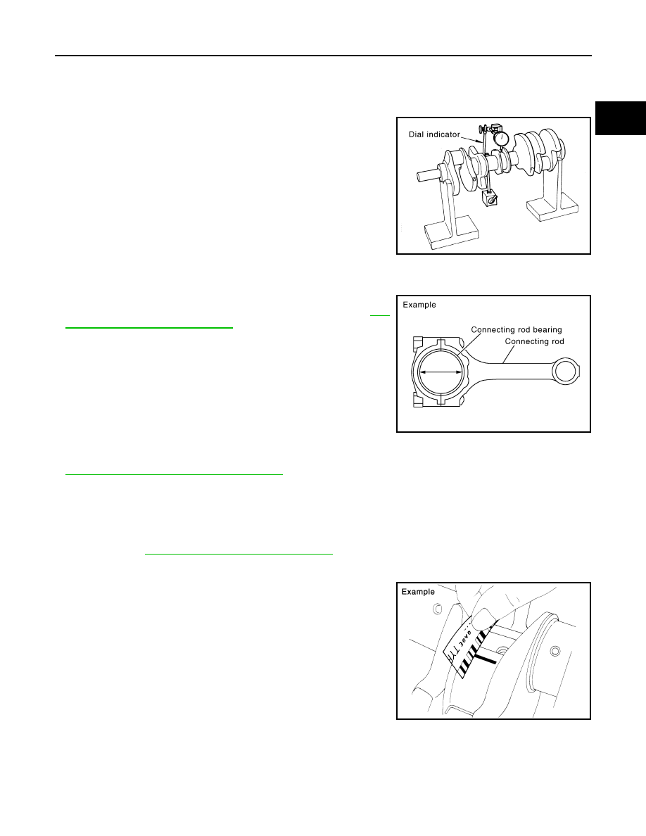
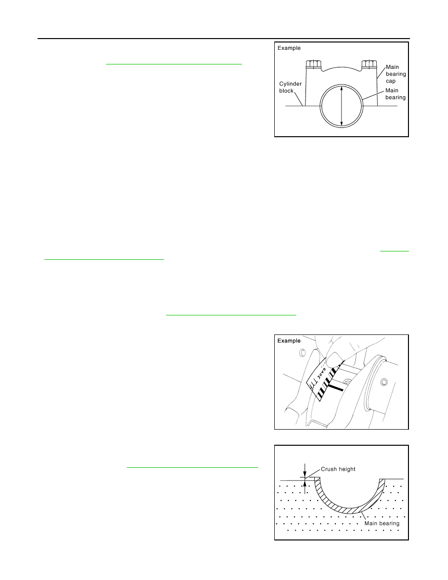
Piston Skirt Diameter
• Measure the outer diameter of piston skirt with micrometer.
• Measure point “H” (Distance from the top): 42 mm (1.65 in)
Piston to Cylinder Bore Clearance
Calculate by piston skirt diameter and cylinder bore inner diameter (direction “X”, position “B”).
(Clearance) = (Cylinder bore inner diameter) – (Piston skirt diameter).
• If the calculated value exceeds the limit, replace piston and piston pin assembly. Refer to
.
Standard inner diameter:
93.000 - 93.030 mm (3.6614 - 3.6626 in)
Wear limit:
0.2 mm (0.008 in)
Out-of-round (Difference between “X” and “Y”):
0.015 mm (0.0006 in)
Taper limit (Difference between “A” and “C”):
0.01 mm (0.0004 in)
Oversize (OS)
: 0.2 mm (0.008 in)
PBIC0123E
PBIC0124E
Standard
: 92.980 - 93.010 mm (3.6606 - 3.6618 in)
PBIC0125E
PBIC0126E
Standard
: 0.010 - 0.030 mm (0.0004 - 0.0012 in)
Limit
: 0.08 mm (0.0031 in)
EM-262
< SERVICE INFORMATION >
[VK45DE]
CYLINDER BLOCK
Re-boring Cylinder Bore
1.
Cylinder bore size is determined by adding piston to cylinder bore clearance to piston skirt diameter.
2.
Install main bearing caps and main bearing, and tighten to the specified torque. Otherwise, cylinder bores
may be distorted in final assembly.
3.
Cut cylinder bores.
NOTE:
• When any cylinder needs boring, all other cylinders must also be bored.
• Do not cut too much out of cylinder bore at a time. Cut only 0.05 mm (0.0020 in) or so in diameter at a
time.
4.
Hone cylinders to obtain the specified piston to cylinder bore clearance.
5.
Measure finished cylinder bore for the out-of-round and taper.
NOTE:
Measurement should be done after cylinder bore cools down.
CRANKSHAFT MAIN JOURNAL DIAMETER
• Measure the outer diameter of crankshaft main journals with micrometer.
• If out of the standard, measure the main bearing oil clearance. Then use undersize bearing. Refer to "MAIN
BEARING OIL CLEARANCE".
CRANKSHAFT PIN JOURNAL DIAMETER
• Measure the outer diameter of crankshaft pin journal with
micrometer.
• If out of the standard, measure the connecting rod bearing oil
clearance. Then use undersize bearing. Refer to "CONNECTING
ROD BEARING OIL CLEARANCE".
CRANKSHAFT OUT-OF-ROUND AND TAPER
• Measure the dimensions at four different points as shown in the
figure on each main journal and pin journal with micrometer.
• Out-of-round is indicated by the difference in the dimensions
between “X” and “Y” at “A” and “B”.
• Taper is indicated by the difference in the dimensions between “A”
and “B” at “X” and “Y”.
• If the measured value exceeds the limit, correct or replace crankshaft.
Re-bored size calculation: D = A + B – C
where,
D: Bored diameter
A: Piston skirt diameter as measured
B: Piston to cylinder bore clearance (standard value)
C: Honing allowance 0.02 mm (0.0008 in)
Standard
: 63.940 - 63.964 mm (2.5173 - 2.5183 in) dia.
Standard
: 51.956 - 51.974 mm (2.0455 - 2.0462 in) dia.
PBIC0127E
Limit:
Out-of-round (Difference between “X” and “Y”)
: 0.015 mm (0.0006 in)
Taper (Difference between “A” and “B”)
: 0.010 mm (0.0004 in)
PBIC1685E
CYLINDER BLOCK
EM-263
< SERVICE INFORMATION >
[VK45DE]
C
D
E
F
G
H
I
J
K
L
M
A
EM
N
P
O
• If corrected, measure the bearing oil clearance of the corrected main journal and/or pin journal. Then select
the main bearing and/or connecting rod bearing. Refer to "MAIN BEARING OIL CLEARANCE" and/or
"CONNECTING ROD BEARING OIL CLEARANCE".
CRANKSHAFT RUNOUT
• Place V-block on precise flat table, and support the journals on the
both end of crankshaft.
• Place dial indicator straight up on the No. 3 journal.
• While rotating crankshaft, read the movement of the pointer on
dial indicator. (Total indicator reading)
• If it exceeds the limit, replace crankshaft.
CONNECTING ROD BEARING OIL CLEARANCE
Method by Calculation
• Install connecting rod bearings to connecting rod and cap, and
tighten connecting rod bolts to the specified torque. Refer to
242, "Disassembly and Assembly"
• Measure the inner diameter of connecting rod bearing with inside
micrometer.
(Bearing oil clearance) = (Connecting rod bearing inner diameter) –
(Crankshaft pin journal diameter)
• If the calculated value exceeds the limit, select proper connecting rod bearing according to connecting rod
big end diameter and crankshaft pin journal diameter to obtain the specified bearing oil clearance. Refer to
EM-250, "How to Select Piston and Bearing"
Method of Using Plastigage
• Remove oil and dust on crankshaft pin journal and the surfaces of each bearing completely.
• Cut plastigage slightly shorter than the bearing width, and place it in crankshaft axial direction, avoiding oil
holes.
• Install connecting rod bearings to connecting rod and cap, and tighten connecting rod bolts to the specified
EM-242, "Disassembly and Assembly"
for the tightening procedure.
CAUTION:
Do not rotate crankshaft.
• Remove connecting rod bearing cap and bearing, and using scale
on plastigage bag, measure the plastigage width.
NOTE:
The procedure when the measured value exceeds the limit is
same as that described in the “Method by Calculation”.
MAIN BEARING OIL CLEARANCE
Method by Calculation
Limit
: 0.10 mm (0.0039 in)
PBIC2378E
Standard
: 0.020 - 0.045 mm (0.0008 - 0.0018 in) (actu-
al clearance)
Limit
: 0.055 mm (0.0022 in)
PBIC1642E
PBIC1149E
EM-264
< SERVICE INFORMATION >
[VK45DE]
CYLINDER BLOCK
• Install main bearings to cylinder block and main bearing caps, and
tighten main bearing cap bolts with main bearing to the specified
torque. Refer to
EM-242, "Disassembly and Assembly"
for the
tightening procedure.
• Measure the inner diameter of main bearing with bore gauge.
(Bearing clearance) = (Main bearing inner diameter) – (Crankshaft main journal diameter)
• If the calculated value exceeds the limit, select proper main bearing according to main bearing inner diame-
ter and crankshaft main journal diameter to obtain the specified bearing oil clearance. Refer to
"How to Select Piston and Bearing"
.
Method of Using Plastigage
• Remove oil and dust on crankshaft main journal and the surfaces of each bearing completely.
• Cut plastigage slightly shorter than the bearing width, and place it in crankshaft axial direction, avoiding oil
holes.
• Install main bearings to cylinder block and main bearing caps, and tighten main bearing bolts with main bear-
ing to the specified torque. Refer to
EM-242, "Disassembly and Assembly"
for the tightening procedure.
CAUTION:
Do not rotate crankshaft.
• Remove main bearing caps and bearings, and using scale on plas-
tigage bag, measure the plastigage width.
NOTE:
The procedure when the measured value exceeds the limit is
same as that described in the “Method by Calculation”.
CRUSH HEIGHT OF MAIN BEARING
• When main bearing cap is removed after being tightened to the
specified torque with main bearings installed, the tip end of bearing
must protrude. Refer to
EM-242, "Disassembly and Assembly"
for
the tightening procedure.
• If the standard is not met, replace main bearings.
CRUSH HEIGHT OF CONNECTING ROD BEARING
PBIC1644E
Standard
No. 1 and 5 journal
:
0.001 - 0.011 mm (0.00004 - 0.0004 in)
No. 2, 3 and 4 journal
:
0.007 - 0.017 mm (0.0003 - 0.0007 in)
Limit
No. 1 and 5 journal
:
0.021 mm (0.0008 in)
No. 2, 3 and 4 journal
:
0.027 mm (0.0011 in)
PBIC1149E
Standard
: There must be crush height.
SEM502G
Нет комментариевНе стесняйтесь поделиться с нами вашим ценным мнением.
Текст