Infiniti FX35 / FX45. Manual — part 380

DTC P0171, P0174 FUEL INJECTION SYSTEM FUNCTION
EC-281
< SERVICE INFORMATION >
[VQ35DE]
C
D
E
F
G
H
I
J
K
L
M
A
EC
N
P
O
OK or NG
OK
>> GO TO 6.
NG
>> GO TO 5.
5.
DETECT MALFUNCTIONING PART
Check the following.
• Fuel pump and circuit (Refer to
.)
• Fuel pressure regulator (Refer to
)
• Fuel lines (Refer to
.)
• Fuel filter for clogging
>> Repair or replace.
6.
CHECK MASS AIR FLOW SENSOR
With CONSULT-III
1.
Install all removed parts.
2.
Check “MASS AIR FLOW” in “DATA MONITOR” mode with CONSULT-III.
With GST
1.
Install all removed parts.
2.
Check mass air flow sensor signal in Service $01 with GST.
OK or NG
OK (With CONSULT-III)>>GO TO 7.
OK (Without COUSULT-II)>>GO TO 8.
NG
>> Check connectors for rusted terminals or loose connections in the mass air flow sensor circuit or
ground. Refer to
.
7.
CHECK FUNCTION OF FUEL INJECTOR
With CONSULT-III
1.
Start engine.
2.
Perform “POWER BALANCE” in “ACTIVE TEST” mode with CONSULT-III.
3.
Make sure that each circuit produces a momentary engine speed drop.
OK or NG
OK
>> GO TO 10.
NG
>> Perform trouble diagnosis for FUEL INJECTOR, refer to
8.
CHECK FUNCTION OF FUEL INJECTOR-I
Without CONSULT-III
1.
Turn ignition switch OFF.
At idling: Approximately 350 kPa (3.57 kg/cm
2
, 51 psi)
2.0 - 6.0 g·m/sec:
at idling
7.0 - 20.0 g·m/sec:
at 2,500 rpm
2.0 - 6.0 g·m/sec:
at idling
7.0 - 20.0 g·m/sec:
at 2,500 rpm
EC-282
< SERVICE INFORMATION >
[VQ35DE]
DTC P0171, P0174 FUEL INJECTION SYSTEM FUNCTION
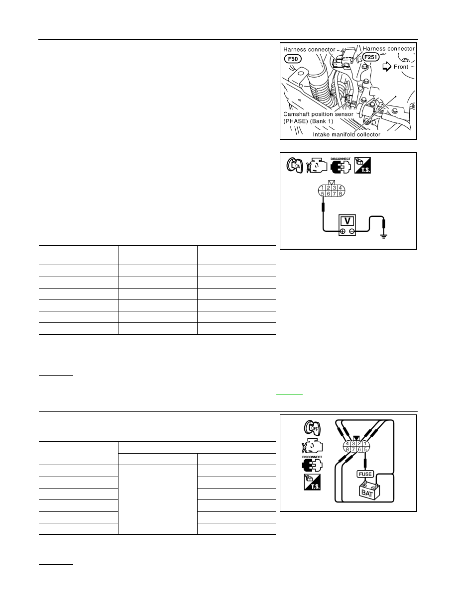
2.
Disconnect harness connectors F50, F251
3.
Turn ignition switch ON.
4.
Check voltage between harness connector F50 terminal 5 and
ground.
5.
Turn ignition switch OFF.
6.
Disconnect ECM harness connector.
7.
Check harness continuity between harness connector F50 and
ECM as follows.
Refer to Wiring Diagram.
8.
Also check harness for short to ground and short to power.
OK or NG
OK
>> GO TO 9.
NG
>> Perform trouble diagnosis for FUEL INJECTOR, refer to
.
9.
CHECK FUNCTION OF FUEL INJECTOR-II
Provide battery voltage between harness connector F251 as follows
and then interrupt it. Listen to each fuel injector operating sound.
OK or NG
PBIB2624E
Voltage: Battery voltage
Cylinder
Harness connector F50
terminal
ECM terminal
1
6
23
2
4
42
3
2
22
4
3
41
5
1
21
6
7
40
Continuity should exist.
PBIB2323E
Cylinder
Harness connector F251 terminal
(+)
(–)
1
5
6
2
4
3
2
4
3
5
1
6
7
Operating sound should exist.
PBIB2497E
DTC P0171, P0174 FUEL INJECTION SYSTEM FUNCTION
EC-283
< SERVICE INFORMATION >
[VQ35DE]
C
D
E
F
G
H
I
J
K
L
M
A
EC
N
P
O
OK
>> GO TO 10.
NG
>> Perform trouble diagnosis for FUEL INJECTOR, refer to
10.
CHECK FUEL INJECTOR
1.
Confirm that the engine is cooled down and there are no fire hazards near the vehicle.
2.
Turn ignition switch OFF.
3.
Reconnect all harness connectors disconnected.
4.
Disconnect all fuel injector harness connectors.
5.
Remove fuel injector gallery assembly. Refer to
.
Keep fuel hose and all fuel injectors connected to fuel injector gallery.
6.
For DTC P0171, reconnect fuel injector harness connectors on bank 1.
For DTC P0174, reconnect fuel injector harness connectors on bank 2.
7.
Disconnect all ignition coil harness connectors.
8.
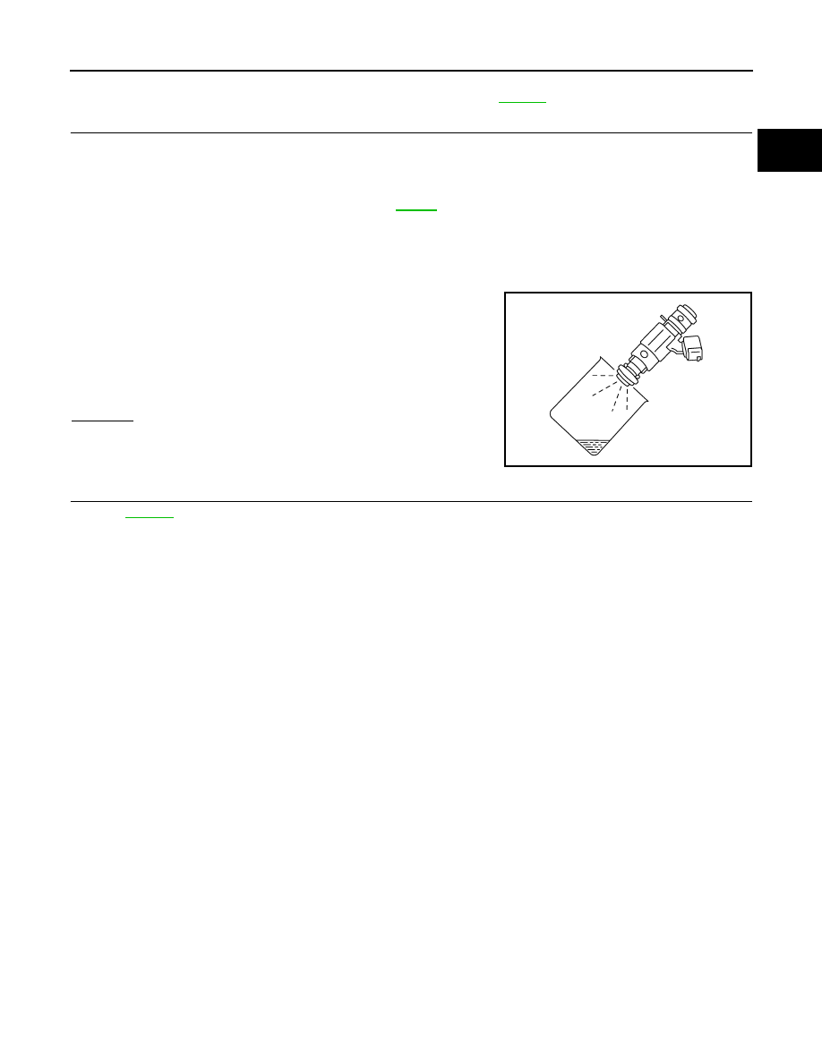
Prepare pans or saucers under each fuel injector.
9.
Crank engine for about 3 seconds.
For DTC P0171, make sure that fuel sprays out from fuel injec-
tors on bank 1.
For DTC P0174, make sure that fuel sprays out from fuel injec-
tors on bank 2.
OK or NG
OK
>> GO TO 11.
NG
>> Replace fuel injectors from which fuel does not spray
out. Always replace O-ring with new ones.
11.
CHECK INTERMITTENT INCIDENT
>> INSPECTION END
Fuel should be sprayed evenly for each fuel injector.
PBIB1726E

EC-284
< SERVICE INFORMATION >
[VQ35DE]
DTC P0172, P0175 FUEL INJECTION SYSTEM FUNCTION
DTC P0172, P0175 FUEL INJECTION SYSTEM FUNCTION
On Board Diagnosis Logic
INFOID:0000000001326105
With the Air-Fuel Mixture Ratio Self-Learning Control, the actual mixture ratio can be brought closely to the
theoretical mixture ratio based on the mixture ratio feedback signal from the air fuel ratio (A/F) sensor 1. The
ECM calculates the necessary compensation to correct the offset between the actual and the theoretical
ratios.
In case the amount of the compensation value is extremely large (the actual mixture ratio is too rich.), the
ECM judges the condition as the fuel injection system malfunction and lights up the MIL (2 trip detection logic).
DTC Confirmation Procedure
INFOID:0000000001609264
NOTE:
If DTC Confirmation Procedure has been previously conducted, always turn ignition switch OFF and wait at
least 10 seconds before conducting the next test.
WITH CONSULT-III
1.
Start engine and warm it up to normal operating temperature.
2.
Turn ignition switch OFF and wait at least 10 seconds.
3.
Turn ignition switch ON and select “SELF-LEARNING CONT” in “WORK SUPPORT” mode with CON-
SULT-III.
4.
Clear the self-learning control coefficient by touching “CLEAR”.
5.
Start engine.
If it is difficult to start engine, the fuel injection system has a malfunction.
Perform the following procedure is advised.
a.
Crank engine while depressing accelerator pedal.
b.
If engine starts, go to .
If engine does not start, remove ignition plugs and check for fouling, etc.
6.
Keep engine at idle for at least 10 minutes.
7.
Check 1st trip DTC.
8.
If 1st trip DTC is detected, go to
If 1st trip DTC is not detected, performing the following procedure is advised.
a.
Turn ignition switch OFF and wait at least 10 seconds.
b.
Start engine and drive the vehicle under the similar conditions to (1st trip) Freeze Frame Data for 10 min-
utes. Refer to the table below.
Hold the accelerator pedal as steady as possible.
The similar conditions to (1st trip) Freeze Frame Data means the vehicle operation that the following con-
ditions should be satisfied at the same time.
Sensor
Input signal to ECM
ECM function
Actuator
Air fuel ration (A/F) sensor 1
Density of oxygen in exhaust gas
(Mixture ratio feedback signal)
Fuel injection
control
Fuel injector
DTC No.
Trouble diagnosis
name
DTC detecting condition
Possible cause
P0172
0172
(Bank 1)
Fuel injection system
too rich
• Fuel injection system does not operate properly.
• The amount of mixture ratio compensation is too
large. (The mixture ratio is too rich.)
• Air fuel ratio (A/F) sensor 1
• Fuel injector
• Exhaust gas leaks
• Incorrect fuel pressure
• Mass air flow sensor
P0175
0175
(Bank 2)
Engine speed
Engine speed in the freeze frame data
±
400 rpm
Vehicle speed
Vehicle speed in the freeze frame data
±
10 km/h (6 MPH)
Нет комментариевНе стесняйтесь поделиться с нами вашим ценным мнением.
Текст