Infiniti FX35 / FX45. Manual — part 661
PRECAUTIONS
EM-161
< SERVICE INFORMATION >
[VK45DE]
C
D
E
F
G
H
I
J
K
L
M
A
EM
N
P
O
Precaution for Assembly and Installation
INFOID:0000000001325756
• Use torque wrench to tighten bolts or nuts to specification.
• When tightening nuts and bolts, as a basic rule, equally tighten in several different steps starting with the
ones in center, then ones on inside and outside diagonally in this order. If the order of tightening is specified,
do exactly as specified.
• Replace with new gasket, packing, oil seal or O-ring.
• Thoroughly wash, clean, and air-blow each part. Carefully check engine oil or engine coolant passages for
any restriction and blockage.
• Guide pins are used for several parts alignment. When replacing and reassembling parts with guide pins,
make sure that guide pins are installed in the original portion.
• Avoid damaging sliding or mating surfaces. Completely remove foreign materials such as cloth lint or dust.
Before assembly, oil sliding surfaces well.
• Release air within route when refilling after draining engine coolant.
• After repairing, start engine and increase engine speed to check engine coolant, fuel, engine oil, and
exhaust gases for leakage.
Parts Requiring Angle Tightening
INFOID:0000000001325757
• Use angle wrench [SST: KV10112100 (BT8653-A)] for the final tightening of the following engine parts:
- Cylinder head bolts
- Main bearing cap bolts
- Connecting rod cap nuts
- Crankshaft pulley bolt (No angle wrench is required as the bolt flange is provided with notches for angle
tightening)
• Do not use a torque value for final tightening.
• The torque value for these parts are for a preliminary step.
• Ensure thread and seat surfaces are clean and coated with engine oil.
Precaution for Liquid Gasket
INFOID:0000000001325758
REMOVAL OF LIQUID GASKET SEALING
• After removing mounting nuts and bolts, separate the mating sur-
face using seal cutter (SST) and remove old liquid gasket sealing.
CAUTION:
Be careful not to damage the mating surfaces.
• Tap seal cutter to insert it, and then slide it by tapping on the side
as shown in the figure.
• In areas where seal cutter (SST) is difficult to use, use plastic ham-
mer to lightly tap the parts, to remove it.
CAUTION:
If for some unavoidable reason tool such as screwdriver is
used, be careful not to damage the mating surfaces.
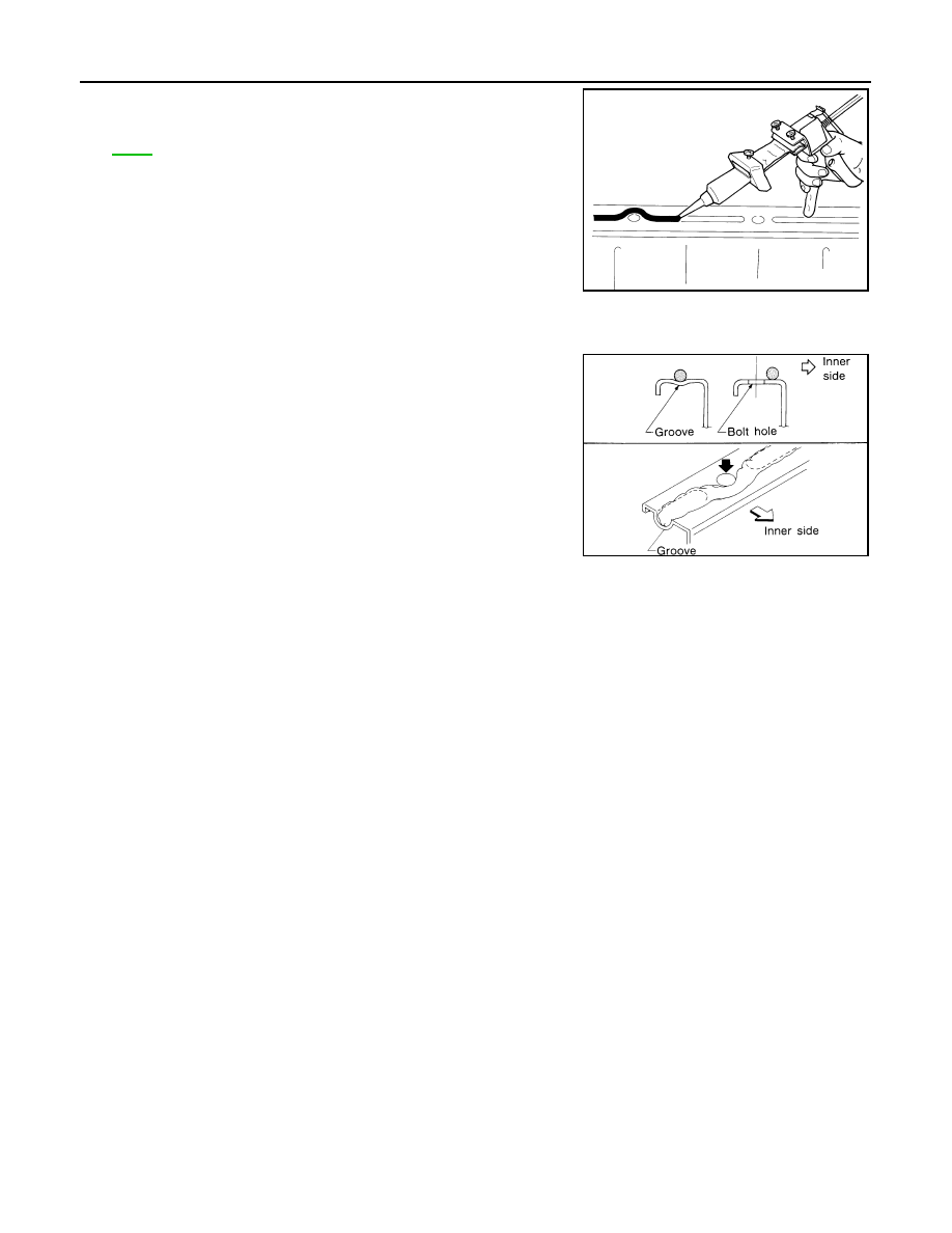
LIQUID GASKET APPLICATION PROCEDURE
1.
Using scraper, remove old liquid gasket adhering to the liquid
gasket application surface and the mating surface.
• Remove liquid gasket completely from the groove of the liquid
gasket application surface, mounting bolts, and bolt holes.
2.
Wipe the liquid gasket application surface and the mating sur-
face with white gasoline (lighting and heating use) to remove
adhering moisture, grease and foreign materials.
PBIC0002E
PBIC0003E
EM-162
< SERVICE INFORMATION >
[VK45DE]
PRECAUTIONS
3.
Attach liquid gasket tube to tube presser (commercial service
tool).
Use Genuine RTV Silicone Sealant or equivalent. Refer to
.
4.
Apply liquid gasket without breaks to the specified location with the specified dimensions.
• If there is a groove for the liquid gasket application, apply liquid gasket to the groove.
• As for the bolt holes, normally apply liquid gasket inside the
holes. Occasionally, it should be applied outside the holes.
Make sure to read the text of this manual.
• Within five minutes of liquid gasket application, install the mat-
ing component.
• If liquid gasket protrudes, wipe it off immediately.
• Do not retighten after the installation.
• Wait 30 minutes or more after installation before refilling
engine with engine oil and engine coolant.
CAUTION:
If there are specific instructions in this manual, observe
them.
EMA0622D
SEM159F
PREPARATION
EM-163
< SERVICE INFORMATION >
[VK45DE]
C
D
E
F
G
H
I
J
K
L
M
A
EM
N
P
O
PREPARATION
Special Service Tool
INFOID:0000000001325759
The actual shapes of Kent-Moore tools may differ from those of special service tools illustrated here.
Tool number
(Kent-Moore No.)
Tool name
Description
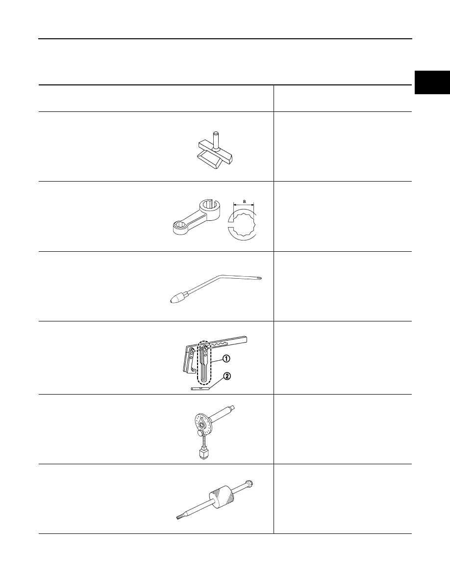
KV10111100
(J–37228)
Seal cutter
Removing steel oil pan and front cover
KV10114400
(J-38365)
Heated oxygen sensor wrench
Loosening or tightening air fuel ratio sensors
and heated oxygen sensors
a: 22 mm (0.87 in)
EG15050500
(J–45402)
Compression gauge adapter
Inspection of compression pressure
KV10116200
(J–26336-A)
Valve spring compressor
1. KV10115900
(J–26336-20)
Attachment
2. KV10109220
(
—
)
Adapter
Disassembling valve mechanism
Part (1) is a component of KV10116200
(J26336-A), but part (2) is not so.
KV10112100
(BT8653-A)
Angle wrench
Tightening bolts for bearing cap, cylinder
head, etc.
KV10114700
(J–38139)
Main bearing cap remover
Removing crankshaft main bearing cap
S-NT046
S-NT636
ZZA1225D
PBIC1650E
S-NT014
ZZA0023D
EM-164
< SERVICE INFORMATION >
[VK45DE]
PREPARATION
Commercial Service Tool
INFOID:0000000001325760
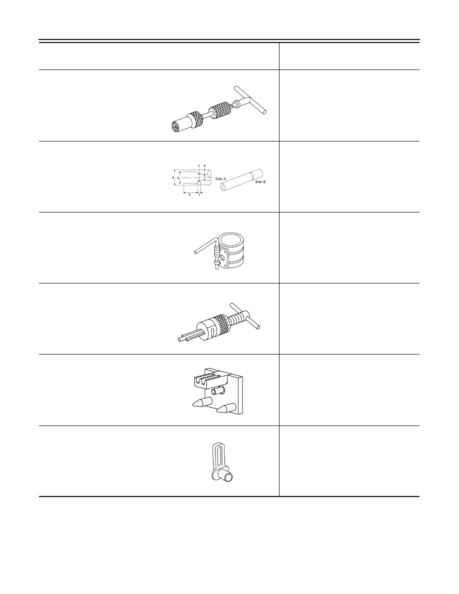
KV10107902
(J–38959)
Valve oil seal puller
Removing valve oil seal
KV10115600
(J–38958)
Valve oil seal drift
Installing valve oil seal
Use side A.
a: 20 (0.79) dia. d: 8 (0.31) dia.
b: 13 (0.51) dia. e: 10.7 (0.421)
c: 10.3 (0.406) dia. f: 5 (0.20)
Unit: mm (in)
EM03470000
(J–8037)
Piston ring compressor
Installing piston assembly into cylinder bore
ST16610001
(J–23907)
Pilot bushing puller
Removing crankshaft pilot converter
—
(J-45476)
Ring gear stopper
Removing and installing crankshaft pulley
—
(J-45488)
Quick connector release
Removing fuel tube quick connectors in en-
gine room
Tool number
(Kent-Moore No.)
Tool name
Description
S-NT011
S-NT603
S-NT044
S-NT045
PBIC1655E
PBIC0198E
Нет комментариевНе стесняйтесь поделиться с нами вашим ценным мнением.
Текст