Infiniti FX35 / FX45. Manual — part 25
AT-28
< SERVICE INFORMATION >
A/T CONTROL SYSTEM
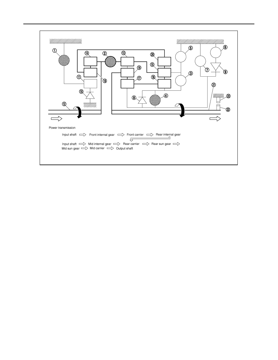
“R” Position
• The front brake fastens the front sun gear.
• The high and low reverse clutch is coupled, and the mid sun gear and rear sun gear are connected.
• The reverse brake fastens the rear carrier.
1.
Front brake
2.
Input clutch
3.
Direct clutch
4.
High and low reverse clutch
5.
Reverse brake
6.
Forward brake
7.
Low coast brake
8.
1st one-way clutch
9.
Forward one-way clutch
10. 3rd one-way clutch
11.
Front sun gear
12. Input shaft
13. Mid internal gear
14. Front internal gear
15. Rear carrier
16. Rear sun gear
17. Mid sun gear
18. Front carrier
19. Mid carrier
20. Rear internal gear
21. Output shaft
22. Parking gear
23. Parking pawl
SCIA4984E
A/T CONTROL SYSTEM
AT-29
< SERVICE INFORMATION >
D
E
F
G
H
I
J
K
L
M
A
B
AT
N
O
P
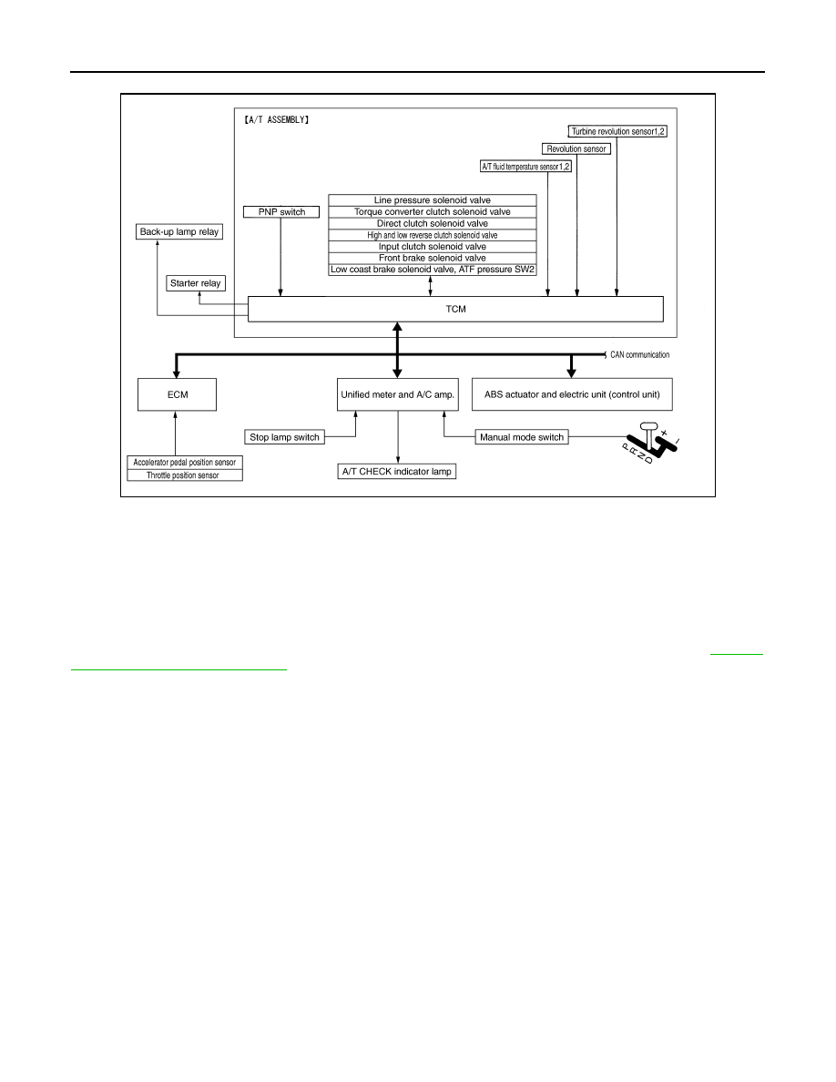
TCM Function
INFOID:0000000001327135
The function of the TCM is to:
• Receive input signals sent from various switches and sensors.
• Determine required line pressure, shifting point, lock-up operation, and engine brake operation.
• Send required output signals to the respective solenoids.
CONTROL SYSTEM OUTLINE
The automatic transmission senses vehicle operating conditions through various sensors or signals. It always
controls the optimum shift position and reduces shifting and lock-up shocks.
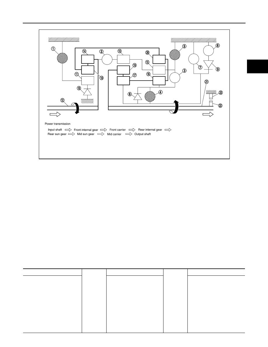
1.
Front brake
2.
Input clutch
3.
Direct clutch
4.
High and low reverse clutch
5.
Reverse brake
6.
Forward brake
7.
Low coast brake
8.
1st one-way clutch
9.
Forward one-way clutch
10. 3rd one-way clutch
11.
Front sun gear
12. Input shaft
13. Mid internal gear
14. Front internal gear
15. Rear carrier
16. Rear sun gear
17. Mid sun gear
18. Front carrier
19. Mid carrier
20. Rear internal gear
21. Output shaft
22. Parking gear
23. Parking pawl
SCIA1519E
SENSORS (or SIGNALS)
⇒
TCM
⇒
ACTUATORS
PNP switch
Accelerator pedal position signal
Closed throttle position signal
Wide open throttle position signal
Engine speed signal
A/T fluid temperature sensor
Revolution sensor
Vehicle speed signal
Manual mode switch signal
Stop lamp switch signal
Turbine revolution sensor
ATF pressure switch
Shift control
Line pressure control
Lock-up control
Engine brake control
Timing control
Fail-safe control
Self-diagnosis
CONSULT-III communication
line
Duet-EA control
CAN system
Input clutch solenoid valve
Direct clutch solenoid valve
Front brake solenoid valve
High and low reverse clutch sole-
noid valve
Low coast brake solenoid valve
Torque converter clutch solenoid
valve
Line pressure solenoid valve
A/T CHECK indicator lamp
Starter relay
Back-up lamp relay
AT-30
< SERVICE INFORMATION >
A/T CONTROL SYSTEM
CONTROL SYSTEM DIAGRAM
CAN Communication
INFOID:0000000001327136
SYSTEM DESCRIPTION
CAN (Controller Area Network) is a serial communication line for real time application. It is an on-vehicle mul-
tiplex communication line with high data communication speed and excellent error detection ability. Many elec-
tronic control units are equipped onto a vehicle, and each control unit shares information and links with other
control units during operation (not independent). In CAN communication, control units are connected with 2
communication lines (CAN-H line, CAN-L line) allowing a high rate of information transmission with less wiring.
Each control unit transmits/receives data but selectively reads required data only. For details, refer to
"CAN System Specification Chart"
JPDIA0484GB
A/T CONTROL SYSTEM
AT-31
< SERVICE INFORMATION >
D
E
F
G
H
I
J
K
L
M
A
B
AT
N
O
P
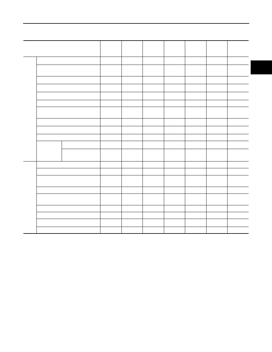
Input/Output Signal of TCM
INFOID:0000000001327137
*1: Spare for vehicle speed sensor·A/T (revolution sensor)
*2: Spare for accelerator pedal position signal
*3: If these input and output signals are different, the TCM triggers the fail-safe function.
*4: Used as a condition for starting self-diagnostics; if self-diagnostics are not started, it is judged that there is some kind of error.
*5: Input by CAN communications
*6: Output by CAN communications
Line Pressure Control
INFOID:0000000001327138
• When an input torque signal equivalent to the engine drive force is sent from the ECM to the TCM, the TCM
controls the line pressure solenoid.
Control item
Line
pressure
control
Vehicle
speed
control
Shift
control
Lock-up
control
Engine
brake
control
Fail-safe
function
(*3)
Self-diag-
nostics
function
Input
Accelerator pedal position signal
(*5)
X
X
X
X
X
X
X
Vehicle speed sensor A/T
(revolution sensor)
X
X
X
X
X
X
X
Vehicle speed sensor MTR
(*1) (*5)
X
Closed throttle position signal
(*5)
X (*2)
X
X
X
X (*4)
Wide open throttle position signal
(*5)
X
X (*4)
Turbine revolution sensor 1
X
X
X
X
X
Turbine revolution sensor 2
(for 4th speed only)
X
X
X
X
X
Engine speed signals
(*5)
X
X
X
X
X
X
X
Stop lamp switch signal
(*5)
X
X
X
X (*4)
A/T fluid temperature sensors 1, 2
X
X
X
X
X
X
ASCD or
ICC
Operation signal
(*5)
X
X
X
Overdrive cancel sig-
nal
(*5)
X
Out-
put
Direct clutch solenoid
X
X
X
X
Input clutch solenoid
X
X
X
X
High and low reverse clutch sole-
noid
X
X
X
X
Front brake solenoid
X
X
X
X
Low coast brake solenoid (ATF
pressure switch 2)
X
X
X
X
X
Line pressure solenoid
X
X
X
X
X
X
X
TCC solenoid
X
X
X
Self-diagnostics table
(*6)
X
Starter relay
X
X
Нет комментариевНе стесняйтесь поделиться с нами вашим ценным мнением.
Текст