Infiniti FX35 / FX45. Manual — part 317
PREPARATION
EC-29
< SERVICE INFORMATION >
[VQ35DE]
C
D
E
F
G
H
I
J
K
L
M
A
EC
N
P
O
PREPARATION
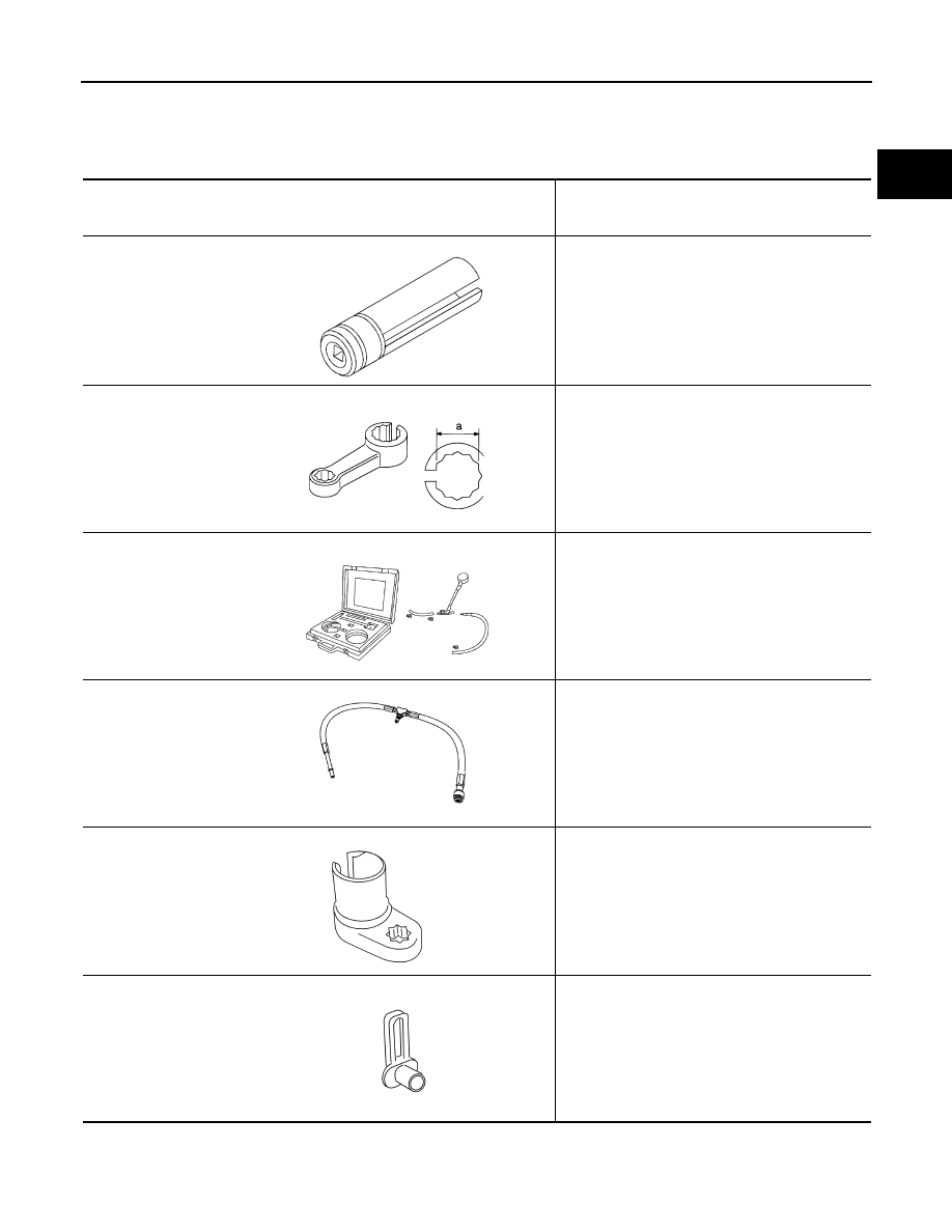
Special Service Tool
INFOID:0000000001325893
The actual shapes of Kent-Moore tools may differ from those of special service tools illustrated here.
Tool number
(Kent-Moore No.)
Tool name
Description
KV10117100
(J-36471-A)
Heated oxygen sensor
wrench
Loosening or tightening heated oxygen sensor
with 22 mm (0.87 in) hexagon nut
KV10114400
(J-38365)
Heated oxygen sensor
wrench
Loosening or tightening air fuel ratio (A/F) sensor
a: 22 mm (0.87 in)
(J-44321)
Fuel pressure gauge
kit
Checking fuel pressure
(J-44321-6)
Fuel pressure adapter
Connecting fuel pressure gauge to quick connec-
tor type fuel lines.
(J-44626)
Air fuel ratio (A/F)
sensor wrench
Loosening or tightening air fuel ratio (A/F) sensor 1
(J-45488)
Quick connector re-
lease
Remove fuel tube quick connectors in engine
room.
S-NT379
S-NT636
LEC642
LBIA0376E
LEM054
PBIC0198E
EC-30
< SERVICE INFORMATION >
[VQ35DE]
PREPARATION
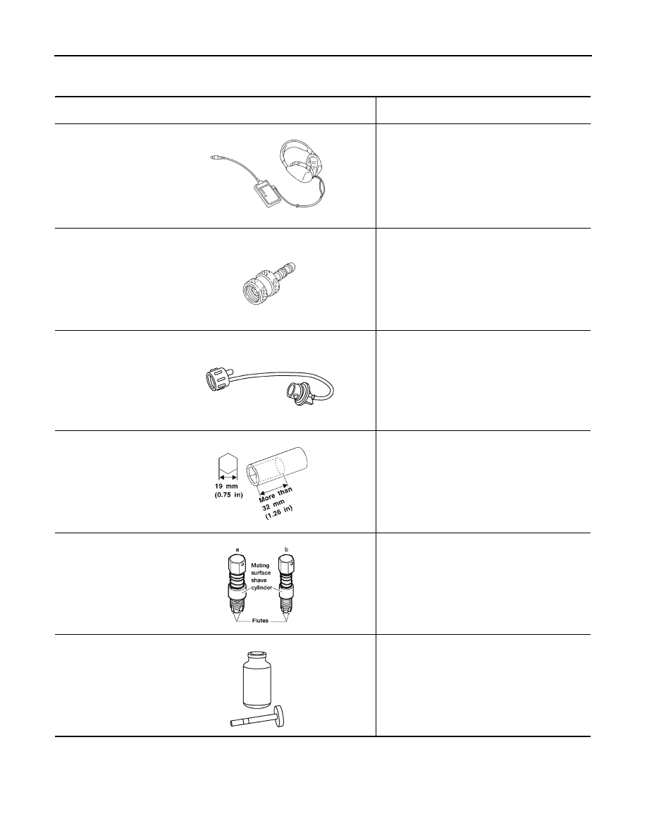
Commercial Service Tool
INFOID:0000000001325894
Tool name
(Kent-Moore No.)
Description
Leak detector
i.e.: (J-41416)
Locating EVAP leak
EVAP service port
adapter
i.e.: (J-41413-OBD)
Applying positive pressure through EVAP service
port
Fuel filler cap adapter
i.e.: (MLR-8382)
Checking fuel tank vacuum relief valve opening
pressure
Socket wrench
Removing and installing engine coolant tempera-
ture sensor
Oxygen sensor thread
cleaner
i.e.: (J-43897-18)
(J-43897-12)
Reconditioning the exhaust system threads before
installing a new oxygen sensor. Use with anti-
seize lubricant shown below.
a: 18 mm diameter with pitch 1.5 mm for Zirco-
nia Oxygen Sensor
b: 12 mm diameter with pitch 1.25 mm for Tita-
nia Oxygen Sensor
Anti-seize lubricant
i.e.: (Permatex
TM
133AR or equivalent
meeting MIL specifica-
tion MIL-A-907)
Lubricating oxygen sensor thread cleaning tool
when reconditioning exhaust system threads.
S-NT703
S-NT704
S-NT815
S-NT705
AEM488
S-NT779

ENGINE CONTROL SYSTEM
EC-31
< SERVICE INFORMATION >
[VQ35DE]
C
D
E
F
G
H
I
J
K
L
M
A
EC
N
P
O
ENGINE CONTROL SYSTEM
Schematic
INFOID:0000000001325895
Multiport Fuel Injection (MFI) System
INFOID:0000000001325896
INPUT/OUTPUT SIGNAL CHART
PBIB2281E

EC-32
< SERVICE INFORMATION >
[VQ35DE]
ENGINE CONTROL SYSTEM
*1: This sensor is not used to control the engine system under normal conditions.
*2: This signal is sent to the ECM through CAN communication line.
*3: ECM determines the start signal status by the signals of engine speed and battery voltage.
SYSTEM DESCRIPTION
The amount of fuel injected from the fuel injector is determined by the ECM. The ECM controls the length of
time the valve remains open (injection pulse duration). The amount of fuel injected is a program value in the
ECM memory. The program value is preset by engine operating conditions. These conditions are determined
by input signals (for engine speed and intake air) from both the crankshaft position sensor and the mass air
flow sensor.
VARIOUS FUEL INJECTION INCREASE/DECREASE COMPENSATION
In addition, the amount of fuel injected is compensated to improve engine performance under various operat-
ing conditions as listed below.
<Fuel increase>
• During warm-up
• When starting the engine
• During acceleration
• Hot-engine operation
• When selector lever is changed from N to D
• High-load, high-speed operation
<Fuel decrease>
• During deceleration
• During high engine speed operation
MIXTURE RATIO FEEDBACK CONTROL (CLOSED LOOP CONTROL)
The mixture ratio feedback system provides the best air-fuel mixture ratio for driveability and emission control.
The three way catalyst 1 can then better reduce CO, HC and NOx emissions. This system uses air fuel ratio
Sensor
Input Signal to ECM
ECM function
Actuator
Crankshaft position sensor (POS)
Engine speed*
3
Piston position
Fuel injection
& mixture ratio
control
Fuel injector
Camshaft position sensor (PHASE)
Mass air flow sensor
Amount of intake air
Engine coolant temperature sensor
Engine coolant temperature
Air fuel ratio (A/F) sensor 1
Density of oxygen in exhaust gas
Throttle position sensor
Throttle position
Accelerator pedal position sensor
Accelerator pedal position
Park/neutral position (PNP) switch
Gear position
Knock sensor
Engine knocking condition
Battery
Battery voltage*
3
Power steering pressure sensor
Power steering operation
Heated oxygen sensor 2*
1
Density of oxygen in exhaust gas
Air conditioner switch
Air conditioner operation*
2
Wheel sensor
Vehicle speed*
2
PBIB3020E
Нет комментариевНе стесняйтесь поделиться с нами вашим ценным мнением.
Текст