Infiniti FX35 / FX45. Manual — part 577

DTC P1572 ASCD BRAKE SWITCH
EC-1069
< SERVICE INFORMATION >
[VK45DE]
C
D
E
F
G
H
I
J
K
L
M
A
EC
N
P
O
TESTING CONDITION:
Steps 4 and 5 may be conducted with the drive wheels lifted in the shop or by driving the vehicle. If a
road test is expected to be easier, it is unnecessary to lift the vehicle.
WITH CONSULT-III
1.
Start engine (VDC switch OFF).
2.
Select “DATA MONITOR” mode with CONSULT-III.
3.
Press MAIN switch and make sure that CRUISE lamp lights up.
4.
Drive the vehicle for at least 5 consecutive seconds under the following conditions.
5.
Check 1st trip DTC.
6.
If 1st trip DTC is detected, go to
EC-1071, "Diagnosis Procedure"
If 1st trip DTC is not detected, go to the following step.
7.
Drive the vehicle for at least 5 consecutive seconds under the following conditions.
8.
Check 1st trip DTC.
9.
If 1st trip DTC is detected, go to
EC-1071, "Diagnosis Procedure"
WITH GST
Follow the procedure “WITH CONSULT-III” above.
VHCL SPEED SE
More than 30 km/h (19 MPH)
Selector lever
Suitable position
VHCL SPEED SE
More than 30 km/h (19 MPH)
Selector lever
Suitable position
Driving location
Depress the brake pedal for more than
five seconds so as not to come off from
the above-mentioned vehicle speed.
EC-1070
< SERVICE INFORMATION >
[VK45DE]
DTC P1572 ASCD BRAKE SWITCH
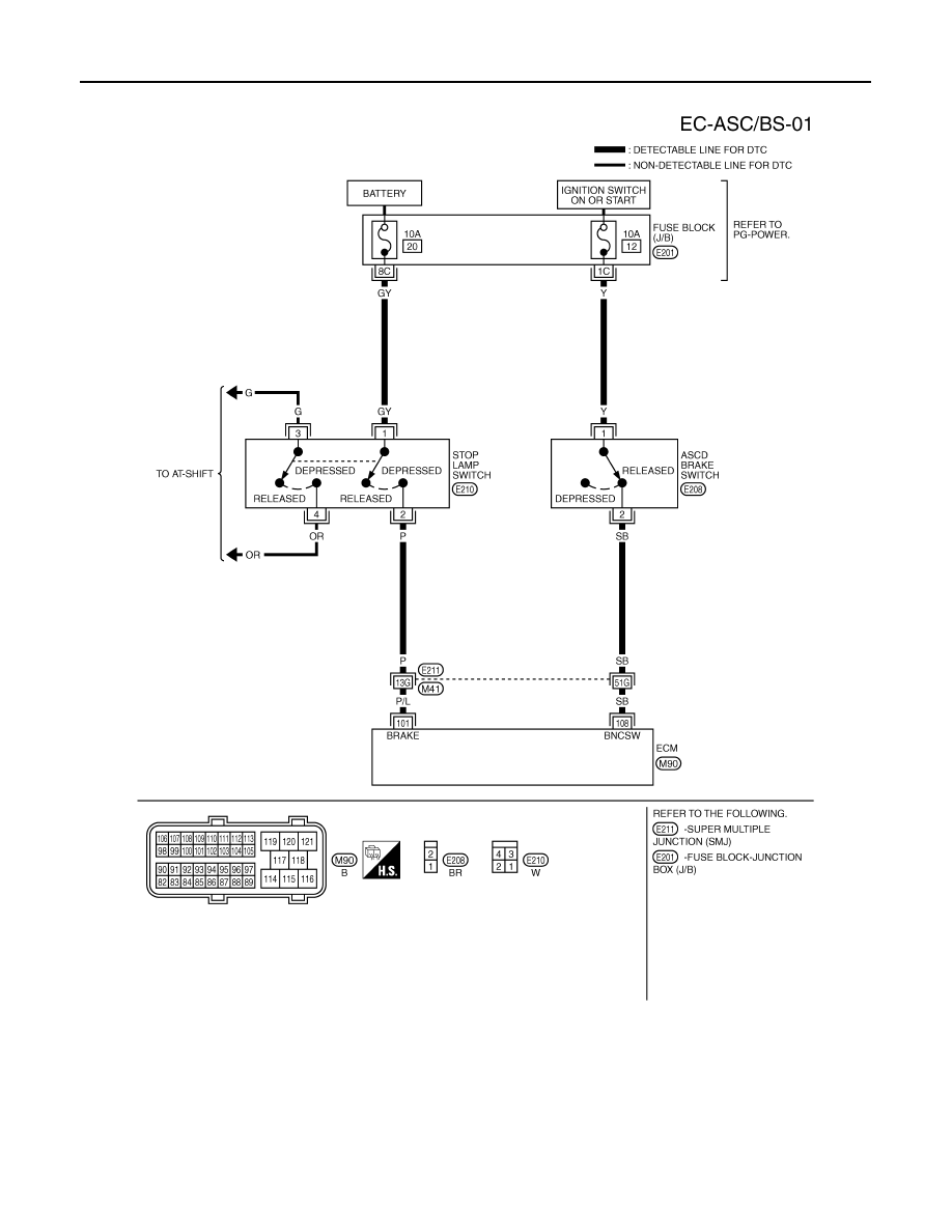
Wiring Diagram
INFOID:0000000001326946
Specification data are reference values and are measured between each terminal and ground.
CAUTION:
Do not use ECM ground terminals when measuring input/output voltage. Doing so may result in dam-
age to the ECM's transistor. Use a ground other than ECM terminals, such as the ground.
TBWM1352E
DTC P1572 ASCD BRAKE SWITCH
EC-1071
< SERVICE INFORMATION >
[VK45DE]
C
D
E
F
G
H
I
J
K
L
M
A
EC
N
P
O
Diagnosis Procedure
INFOID:0000000001326947
1.
CHECK OVERALL FUNCTION-I
With CONSULT-III
1.
Turn ignition switch ON.
2.
Select “BRAKE SW1” in “DATA MONITOR” mode with CONSULT-III.
3.
Check “BRAKE SW1” indication under the following conditions.
Without CONSULT-III
1.
Turn ignition switch ON.
2.
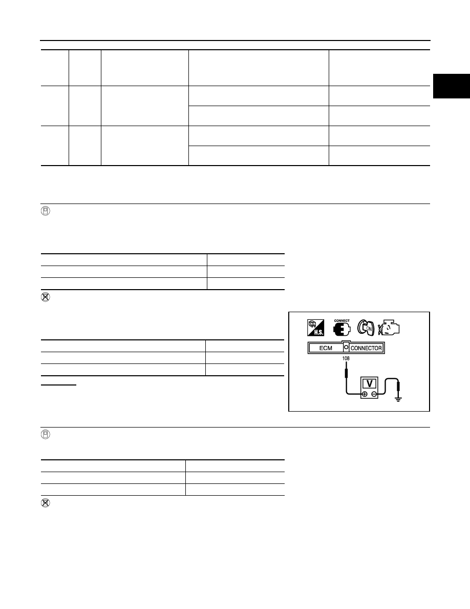
Check voltage between ECM terminal 108 and ground under the
following conditions.
OK or NG
OK
>> GO TO 2.
NG
>> GO TO 3.
2.
CHECK OVERALL FUNCTION-II
With CONSULT-III
Check “BRAKE SW2” indication in “DATA MONITOR” mode.
Without CONSULT-III
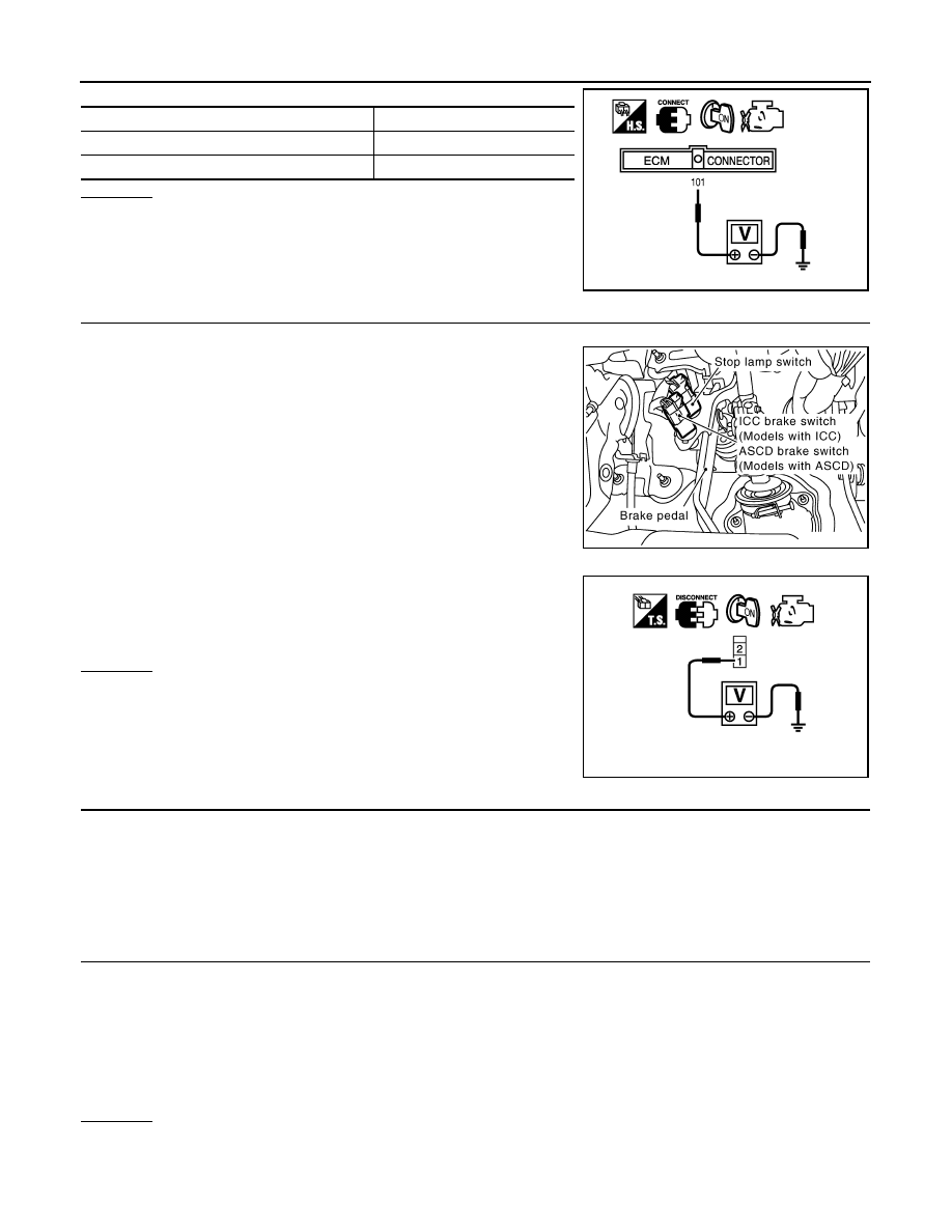
Check voltage between ECM terminal 101 and ground under the following conditions.
TER-
MI-
NAL
NO.
WIRE
COLOR
ITEM
CONDITION
DATA (DC Voltage)
101
P/L
Stop lamp switch
[Ignition switch: OFF]
• Brake pedal: Fully released
Approximately 0V
[Ignition switch: OFF]
• Brake pedal: Slightly depressed
BATTERY VOLTAGE
(11 - 14V)
108
SB
ASCD brake switch
[Ignition switch: ON]
• Brake pedal: Slightly depressed
Approximately 0V
[Ignition switch: ON]
• Brake pedal: Fully released
BATTERY VOLTAGE
(11 - 14V)
CONDITION
INDICATION
When brake pedal: Slightly depressed
OFF
When brake pedal: Fully released
ON
CONDITION
VOLTAGE
When brake pedal: Slightly depressed
Approximately 0V
When brake pedal: Fully released
Battery voltage
MBIB0061E
CONDITION
INDICATION
When brake pedal: Fully released
OFF
When brake pedal: Slightly depressed
ON
EC-1072
< SERVICE INFORMATION >
[VK45DE]
DTC P1572 ASCD BRAKE SWITCH
OK or NG
OK
>> GO TO 13.
NG
>> GO TO 8.
3.
CHECK ASCD BRAKE SWITCH POWER SUPPLY CIRCUIT
1.
Turn ignition switch OFF.
2.
Disconnect ASCD brake switch harness connector.
3.
Turn ignition switch ON.
4.
Check voltage between ASCD brake switch terminal 1 and
ground with CONSULT-III or tester.
OK or NG
OK
>> GO TO 5.
NG
>> GO TO 4.
4.
DETECT MALFUNCTIONING PART
Check the following.
• Fuse block (J/B) connector E201
• 10A fuse
• Harness for open or short between ASCD brake switch and fuse
>> Repair open circuit or short to ground or short to power in harness or connectors.
5.
CHECK ASCD BRAKE SWITCH INPUT SIGNAL CIRCUIT FOR OPEN AND SHORT
1.
Turn ignition switch OFF.
2.
Disconnect ECM harness connector.
3.
Check harness continuity between ECM terminal 108 and ASCD brake switch terminal 2.
Refer to Wiring Diagram.
4.
Also check harness for short to ground and short to power.
OK or NG
OK
>> GO TO 7.
NG
>> GO TO 6.
CONDITION
VOLTAGE
When brake pedal: Fully released
Approximately 0V
When brake pedal: Slightly depressed
Battery voltage
PBIB1537E
PBIB2558E
Voltage: Battery voltage
PBIB0857E
Continuity should exist.
Нет комментариевНе стесняйтесь поделиться с нами вашим ценным мнением.
Текст