Infiniti FX35 / FX45. Manual — part 2
ACS-2
DTC 104 LASER AIMING INCMP . . . . . . ..
DTC 107 LASER COMM FAIL . . . . . . . ...
DTC 109 LASER HIGH TEMP . . . . . . . ...
TROUBLE DIAGNOSIS FOR SYMPTOMS . ...
Symptom Chart . . . . . . . . . . . . . ...
Symptom 1 MAIN Switch Does Not Turn ON
Symptom 2 ICC System Cannot Be Set (MAIN
Switch Turns ON/OFF) . . . . . . . . . . ...
Symptom 5 Chime Does Not Sound . . . . . ...
Symptom 6 Driving Force Is Hunting . . . . . ..
Symptom 7 ICC System Frequently Cannot De-
tect the Vehicle Ahead/ Detection Zone Is Short .
Symptom 8 the System Does Not Detect the Vehi-
cle Ahead at All . . . . . . . . . . . . . ...
SELF-DIAGNOSIS BY ICC SYSTEM DISPLAY
WILL NOT RUN . . . . . . . . . . . . . ..
ELECTRICAL COMPONENT INSPECTION . .
ICC Steering Switch . . . . . . . . . . . .
Booster Solenoid . . . . . . . . . . . . . .
Release Switch . . . . . . . . . . . . . ...
ICC Brake Switch and Stop Lamp Switch . . . ...
ICC Brake Hold Relay . . . . . . . . . . . .
REMOVAL AND INSTALLATION . . . . . .
ICC Unit . . . . . . . . . . . . . . . . ..
ICC Sensor . . . . . . . . . . . . . . . .
AUTOMATIC SPEED CONTROL DEVICE (ASCD)
ACS-3
< SERVICE INFORMATION >
[ASCD]
C
D
E
F
G
H
I
J
L
M
A
B
ACS
N
O
P
SERVICE INFORMATION
AUTOMATIC SPEED CONTROL DEVICE (ASCD)
Description
INFOID:0000000001328801
Regarding the information for ASCD system, refer to
ACS-4
< SERVICE INFORMATION >
[ICC]
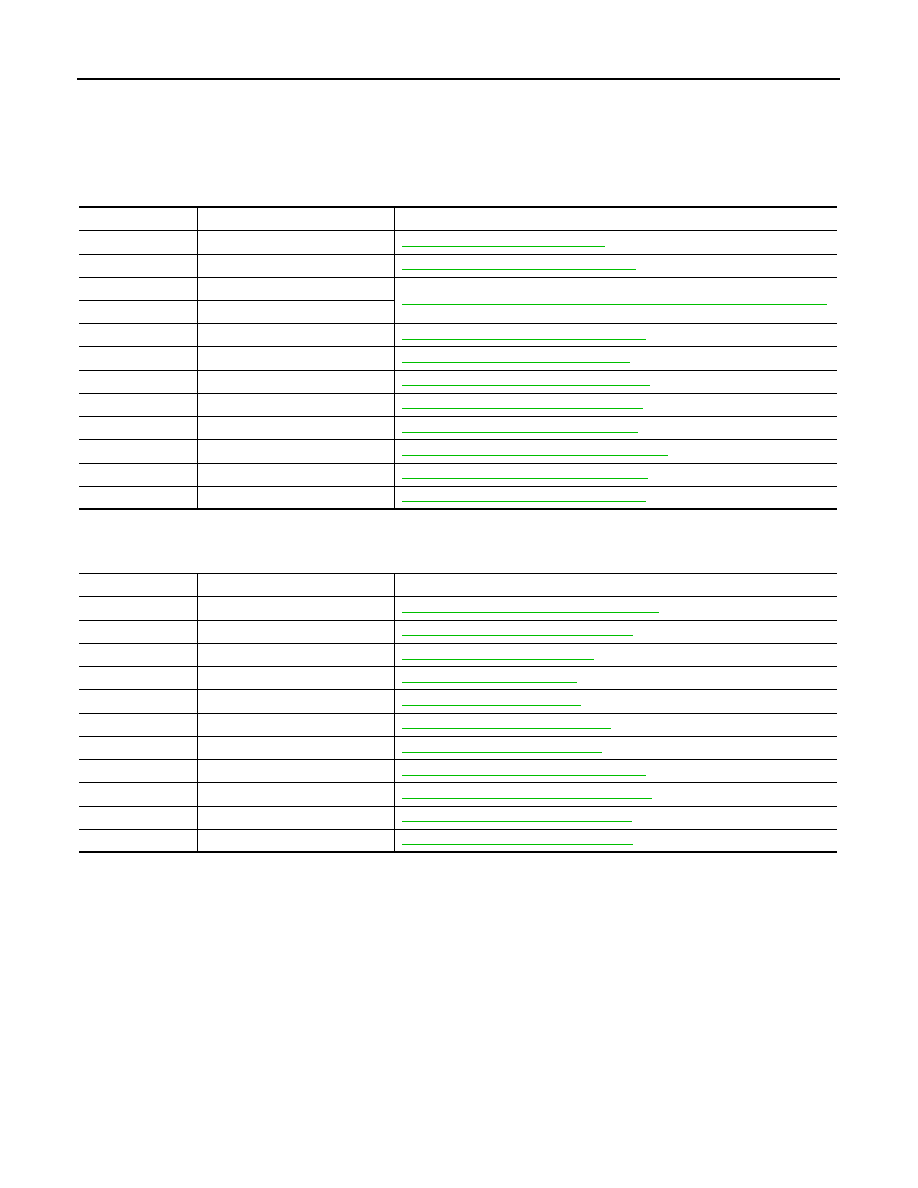
DTC INDEX
SERVICE INFORMATION
DTC INDEX
DTC 11 - 65
INFOID:0000000001544468
DTC 74 - 109
INFOID:0000000001544469
DTC
Items (CONSULT screen terms)
Reference
11
CONTROL UNIT
20
CAN COMM CIRCUIT
ACS-36, "DTC 20 CAN COMM CIRCUIT"
31
POWER SUPPLY CIR
ACS-37, "DTC 31 POWER SUPPLY CIR, DTC 34 POWER SUPPLY CIR 2"
34
POWER SUPPLY CIR 2
41
VHCL SPEED SE CIRC
ACS-37, "DTC 41 VHCL SPEED SE CIRC"
43
ABS/TCS/VDC CIRC
ACS-38, "DTC 43 ABS/TCS/VDC CIRC"
45
BRAKE SW/STOP L SW
ACS-38, "DTC 45 BRAKE SW/STOP L SW"
46
OPERATION SW CIRC
ACS-40, "DTC 46 OPERATION SW CIRC"
61
PRESS SEN SIRCUIT
ACS-41, "DTC 61 PRESS SEN CIRCUIT"
62
BOOSTER SOL/V CIRCUIT
ACS-42, "DTC 62 BOOSTER SOL/V CIRCUIT"
63
RELEASE SW CIRCUIT
ACS-43, "DTC 63 RELEASE SW CIRCUIT"
65
PRESSURE CONTROL
ACS-45, "DTC 65 PRESSURE CONTROL"
DTC
Items (CONSULT screen terms)
Reference
74
LASER BEAM OFF CNTR
ACS-45, "DTC 74 LASER BEAM OFF CNTR"
90
STOP LAMP RLY FIX
ACS-46, "DTC 90 STOP LAMP RLY FIX"
92
ECM CIRCUIT
96
NP RANGE
97
AT CIRCUIT
98
GEAR POSITION
ACS-52, "DTC 98 GEAR POSITION"
102
RADAR STAIN
103
LASER SENSOR FAIL
ACS-53, "DTC 103 LASER SENSOR FAIL"
104
LASER AIMING INCMP
ACS-54, "DTC 104 LASER AIMING INCMP"
107
LASER COMM FAIL
ACS-54, "DTC 107 LASER COMM FAIL"
109
LASER HIGH TEMP
PRECAUTIONS
ACS-5
< SERVICE INFORMATION >
[ICC]
C
D
E
F
G
H
I
J
L
M
A
B
ACS
N
O
P
PRECAUTIONS
Precaution for Supplemental Restraint System (SRS) "AIR BAG" and "SEAT BELT
PRE-TENSIONER"
INFOID:0000000001612901
The Supplemental Restraint System such as “AIR BAG” and “SEAT BELT PRE-TENSIONER”, used along
with a front seat belt, helps to reduce the risk or severity of injury to the driver and front passenger for certain
types of collision. This system includes seat belt switch inputs and dual stage front air bag modules. The SRS
system uses the seat belt switches to determine the front air bag deployment, and may only deploy one front
air bag, depending on the severity of a collision and whether the front occupants are belted or unbelted.
Information necessary to service the system safely is included in the “SUPPLEMENTAL RESTRAINT SYS-
TEM” and “SEAT BELTS” of this Service Manual.
WARNING:
• To avoid rendering the SRS inoperative, which could increase the risk of personal injury or death in
the event of a collision which would result in air bag inflation, all maintenance must be performed by
an authorized NISSAN/INFINITI dealer.
• Improper maintenance, including incorrect removal and installation of the SRS, can lead to personal
injury caused by unintentional activation of the system. For removal of Spiral Cable and Air Bag
Module, see the “SUPPLEMENTAL RESTRAINT SYSTEM”.
• Do not use electrical test equipment on any circuit related to the SRS unless instructed to in this
Service Manual. SRS wiring harnesses can be identified by yellow and/or orange harnesses or har-
ness connectors.
Precaution for ICC System Service
INFOID:0000000001328803
• Never look straight into the laser beam discharger when adjusting laser beam aiming.
• Turn the MAIN switch OFF in conditions similar to driving, such as free rollers or a chassis dynamometer.
• Do not use the ICC sensor removing from vehicle, disassemble, or remodel the sensor.
• Erase DTC when replacing parts of ICC system, then check the operation of ICC system after adjusting laser
beam aiming if necessary.
Нет комментариевНе стесняйтесь поделиться с нами вашим ценным мнением.
Текст