Infiniti FX35 / FX45. Manual — part 45

AT-108
< SERVICE INFORMATION >
DTC P0720 VEHICLE SPEED SENSOR A/T (REVOLUTION SENSOR)
DTC P0720 VEHICLE SPEED SENSOR A/T (REVOLUTION SENSOR)
Description
INFOID:0000000001327196
The revolution sensor detects the revolution of the parking gear and emits a pulse signal. The pulse signal is
sent to the TCM which converts it into vehicle speed.
CONSULT-III Reference Value in Data Monitor Mode
INFOID:0000000001327197
On Board Diagnosis Logic
INFOID:0000000001327198
Diagnostic trouble code “P0720 VEH SPD SEN/CIR AT” with CONSULT-III or 1st judgement flicker without
CONSULT-III is detected under the following conditions.
• When TCM does not receive the proper voltage signal from the sensor.
• After ignition switch is turned ON, irregular signal input from vehicle speed sensor MTR before the vehicle
starts moving.
Possible Cause
INFOID:0000000001327199
• Harness or connectors
(Sensor circuit is open or shorted.)
• Revolution sensor
• Vehicle speed sensor MTR
DTC Confirmation Procedure
INFOID:0000000001327200
CAUTION:
• Always drive vehicle at a safe speed.
• Be careful not to rev engine into the red zone on the tachometer.
NOTE:
If “DTC Confirmation Procedure” has been previously performed, always turn ignition switch OFF and
wait at least 10 seconds before performing the next test.
After the repair, perform the following procedure to confirm the malfunction is eliminated.
WITH CONSULT-III
1.
Turn ignition switch ON.
2.
Select “ECU INPUT SIGNALS” in “DATA MONITOR” mode for “TRANSMISSION” with CONSULT-III.
3.
Touch “START”.
4.
Drive vehicle and check for an increase of “VHCL/S SE-A/T” value in response to “VHCL/S SE-MTR”
value.
If the check result is NG, go to
If the check result is OK, go to following step.
5.
Select “SELECTION FROM MENU” in “DATA MONITOR” mode for “TRANSMISSION” with CONSULT-III
and check monitor “VHCL/S SE-A/T”, “ACCELE POSI”, “ENGINE SPEED” and “SLCT LVR POSI”.
6.
Start engine and maintain the following conditions for at least 5 consecutive seconds.
VHCL/S SE-A/T: 30 km/h (19 MPH) or more
ACCELE POSI: More than 1.0/8
SLCT LVR POSI: “D” position
Driving location: Driving the vehicle uphill (increased engine load) will help maintain the driving
conditions required for this test.
If the check result is NG, go to
If the check result is OK, go to following step.
7.
Maintain the following conditions for at least 5 consecutive seconds.
ENGINE SPEED: 3,500 rpm or more
ACCELE POSI: More than 1.0/8
SLCT LVR POSI: “D” position
Driving location: Driving the vehicle uphill (increased engine load) will help maintain the driving
conditions required for this test.
Item name
Condition
Display value
VHCL/S SE-A/T
During driving
Approximately matches the speedometer reading.
DTC P0720 VEHICLE SPEED SENSOR A/T (REVOLUTION SENSOR)
AT-109
< SERVICE INFORMATION >
D
E
F
G
H
I
J
K
L
M
A
B
AT
N
O
P
8.
If DTC is detected, go to
WITH GST
Follow the procedure “WITH CONSULT-III”.
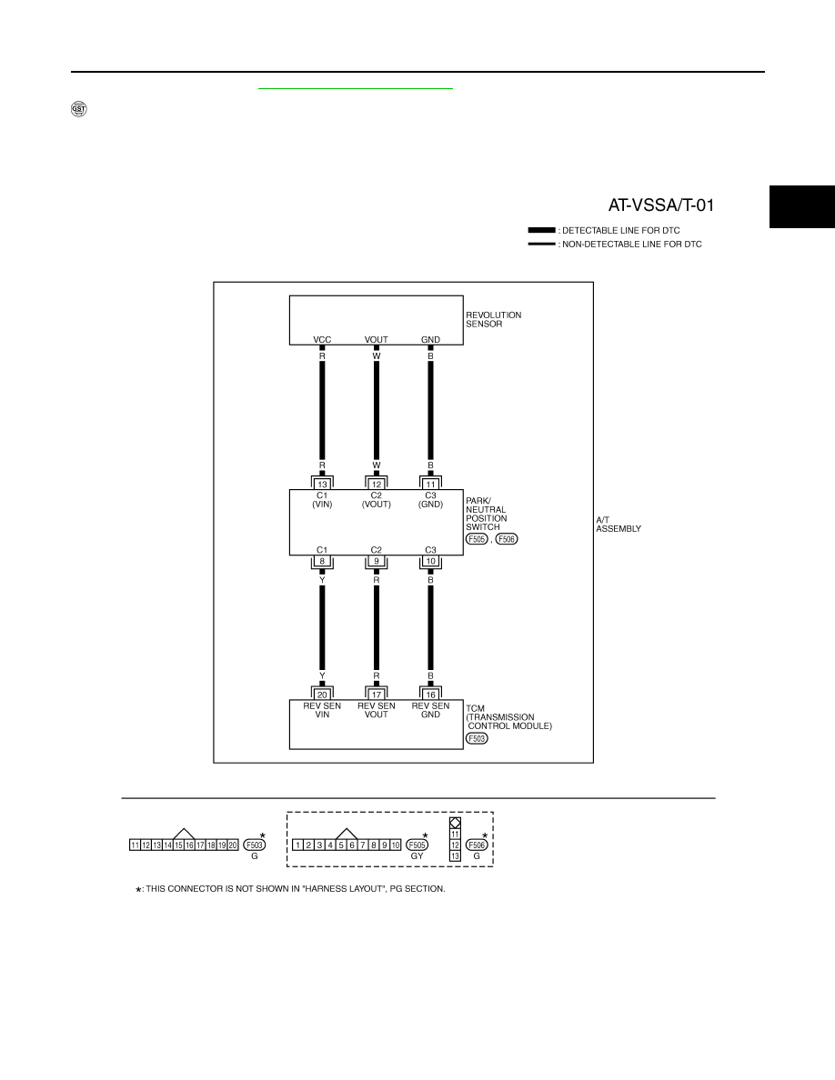
Wiring Diagram - AT - VSSA/T
INFOID:0000000001327201
TCWM0249E
AT-110
< SERVICE INFORMATION >
DTC P0720 VEHICLE SPEED SENSOR A/T (REVOLUTION SENSOR)
Diagnosis Procedure
INFOID:0000000001327202
1.
CHECK INPUT SIGNAL
With CONSULT-III
1.
Turn ignition switch ON.
2.
Select “ECU INPUT SIGNALS” in “DATA MONITOR” mode for “TRANSMISSION” with CONSULT-III.
3.
Start engine.
4.
Read out the value of “VHCL/S SE-A/T” while driving.
Check the value changes according to driving speed.
OK or NG
OK
>> GO TO 6.
NG
>> GO TO 2.
2.
CHECK TCM POWER SUPPLY AND GROUND CIRCUIT
Check TCM power supply and ground circuit. Refer to
OK or NG
OK
>> GO TO 3.
NG
>> Repair or replace damaged parts.
3.
DETECT MALFUNCTIONING ITEM
Check A/T assembly harness connector pin terminals for damage or loose connection with harness connector.
OK or NG
OK
>> GO TO 4.
NG
>> Repair or replace damaged parts.
4.
CHECK SUB-HARNESS
1.
Remove control valve with TCM. Refer to
AT-215, "Control Valve with TCM and A/T Fluid Temperature
.
2.
Disconnect park/neutral position switch connector and TCM connector.
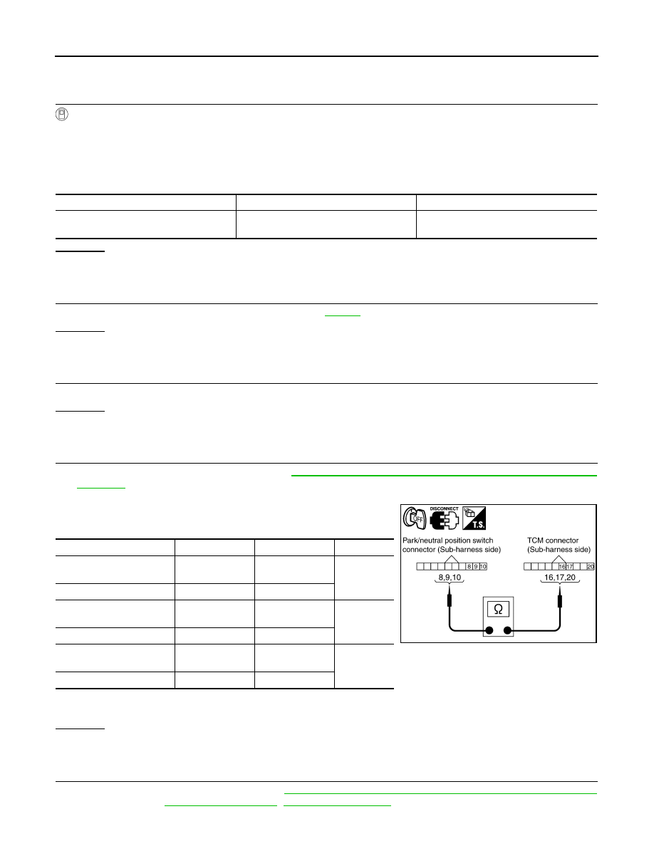
3.
Check continuity between park/neutral position switch connector
terminals and TCM connector terminals.
4.
If OK, check harness for short to ground and short to power.
5.
Reinstall any part removed.
OK or NG
OK
>> GO TO 5.
NG
>> Replace open circuit or short to ground and short to power in harness or connectors.
5.
REPLACE THE REVOLUTION SENSOR AND CHECK DTC
1.
Replace the revolution sensor. Refer to
AT-233, "Revolution Sensor Component (2WD Models Only)"
(2WD models) or
(AWD models).
Item name
Condition
Display value
VHCL/S SE-A/T
During driving
Approximately matches the speedometer
reading.
Item
Connector
Terminal
Continuity
Park/neutral position switch
connector
F505
8
Yes
TCM connector
F503
20
Park/neutral position switch
connector
F505
9
Yes
TCM connector
F503
17
Park/neutral position switch
connector
F505
10
Yes
TCM connector
F503
16
SCIA5458E

DTC P0720 VEHICLE SPEED SENSOR A/T (REVOLUTION SENSOR)
AT-111
< SERVICE INFORMATION >
D
E
F
G
H
I
J
K
L
M
A
B
AT
N
O
P
2.
AT-108, "DTC Confirmation Procedure"
OK or NG
OK
>> INSPECTION END
NG
>> Replace the control valve with TCM. Refer to
AT-215, "Control Valve with TCM and A/T Fluid Tem-
.
6.
CHECK DTC
Perform
AT-108, "DTC Confirmation Procedure"
.
OK or NG
OK
>> INSPECTION END
NG
>> GO TO 2.
Нет комментариевНе стесняйтесь поделиться с нами вашим ценным мнением.
Текст