Infiniti FX35 / FX45. Manual — part 500
DTC P0101 MAF SENSOR
EC-761
< SERVICE INFORMATION >
[VK45DE]
C
D
E
F
G
H
I
J
K
L
M
A
EC
N
P
O
DTC P0101 MAF SENSOR
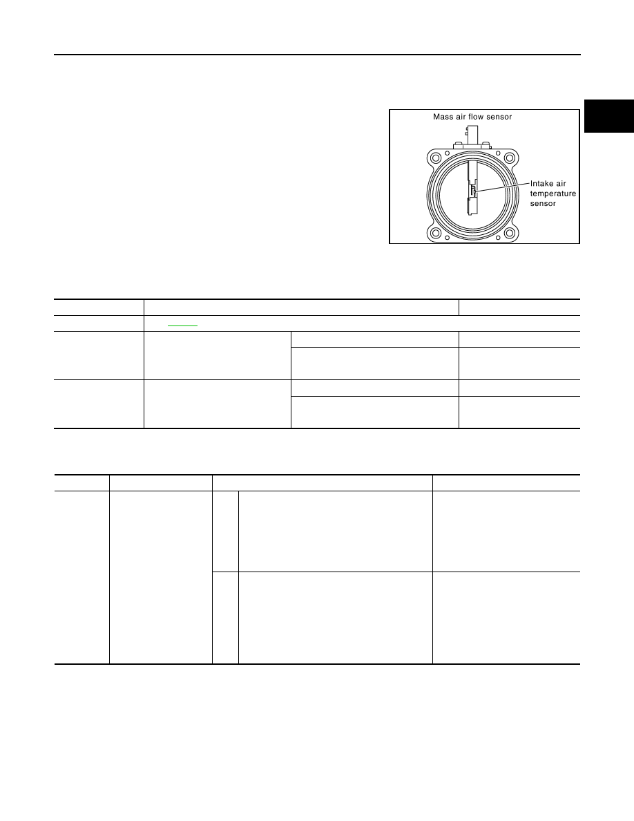
Component Description
INFOID:0000000001326586
The mass air flow sensor is placed in the stream of intake air. It mea-
sures the intake flow rate by measuring a part of the entire intake
flow. The mass air flow sensor controls the temperature of the hot
wire to a certain amount. The heat generated by the hot wire is
reduced as the intake air flows around it. The more air, the greater
the heat loss.
Therefore, the electric current supplied to hot wire is changed to
maintain the temperature of the hot wire as air flow increases. The
ECM detects the air flow by means of this current change.
CONSULT-III Reference Value in Data Monitor Mode
INFOID:0000000001326587
Specification data are reference values.
On Board Diagnosis Logic
INFOID:0000000001326588
DTC Confirmation Procedure
INFOID:0000000001326589
Perform PROCEDURE FOR MALFUNCTION A first.
If DTC cannot be confirmed, perform PROCEDURE FOR MALFUNCTION B.
NOTE:
If DTC Confirmation Procedure has been previously conducted, always turn ignition switch OFF and wait at
least 10 seconds before conducting the next test.
PROCEDURE FOR MALFUNCTION A
NOTE:
PBIB1604E
MONITOR ITEM
CONDITION
SPECIFICATION
MAS A/F SE-B1
See
CAL/LD VALUE
• Engine: After warming up
• Selector lever: P or N
• Air conditioner switch: OFF
• No load
Idle
14% - 33%
2,500 rpm
12% - 25%
MASS AIRFLOW
• Engine: After warming up
• Selector lever: P or N
• Air conditioner switch: OFF
• No load
Idle
2.0 - 6.0 g·m/s
2,500 rpm
7.0 - 20.0 g·m/s
DTC No.
Trouble diagnosis name
DTC detecting condition
Possible cause
P0101
0101
Mass air flow sensor cir-
cuit range/performance
A)
A high voltage from the sensor is sent to ECM
under light load driving condition.
• Harness or connectors
(The sensor circuit is open or
shorted.)
• Mass air flow sensor
• EVAP control system pressure
sensor
• Intake air temperature sensor
B)
A low voltage from the sensor is sent to ECM un-
der heavy load driving condition.
• Harness or connectors
(The sensor circuit is open or
shorted.)
• Intake air leaks
• Mass air flow sensor
• EVAP control system pressure
sensor
• Intake air temperature sensor
EC-762
< SERVICE INFORMATION >
[VK45DE]
DTC P0101 MAF SENSOR
If engine will not start or stops soon, wait at least 10 seconds with engine stopped (Ignition switch ON) instead
of running engine at idle speed.
1.
Start engine and warm it up to normal operating temperature.
2.
Run engine for at least 10 seconds at idle speed.
3.
Check 1st trip DTC.
4.
If 1st trip DTC is detected, go to
PROCEDURE FOR MALFUNCTION B
CAUTION:
Always drive vehicle at a safe speed.
With CONSULT-III
1.
Start engine and warm it up to normal operating temperature.
If engine cannot be started, go to
2.
Select “DATA MONITOR” mode with CONSULT-III.
3.
Check the voltage of “MAS A/F SE-B1” with “DATA MONITOR”.
4.
Increases engine speed to about 4,000 rpm.
5.
Monitor the linear voltage rise in response to engine speed
increases.
If NG, go to
If OK, go to following step.
6.
Maintain the following conditions for at least 10 consecutive sec-
onds.
7.
Check 1st trip DTC.
8.
If 1st trip DTC is detected, go to
.
Overall Function Check
INFOID:0000000001326590
PROCEDURE FOR MALFUNCTION B
Use this procedure to check the overall function of the mass air flow sensor circuit. During this check, a DTC
might not be confirmed.
With GST
1.
Start engine and warm it up to normal operating temperature.
2.
Select “Service $01” with GST.
3.
Check the mass air flow sensor signal with “Service $01”.
4.
Check for linear mass air flow sensor signal value rise in
response to increases to about 4,000 rpm in engine speed.
5.
If NG, go to
ENG SPEED
More than 2,000 rpm
THRTL SEN 1
More than 3V
THRTL SEN 2
More than 3V
Selector lever
Suitable position
Driving location
Driving vehicle uphill (Increased engine load) will help
maintain the driving conditions required for this test.
PBIB3457E
SEF534P
DTC P0101 MAF SENSOR
EC-763
< SERVICE INFORMATION >
[VK45DE]
C
D
E
F
G
H
I
J
K
L
M
A
EC
N
P
O
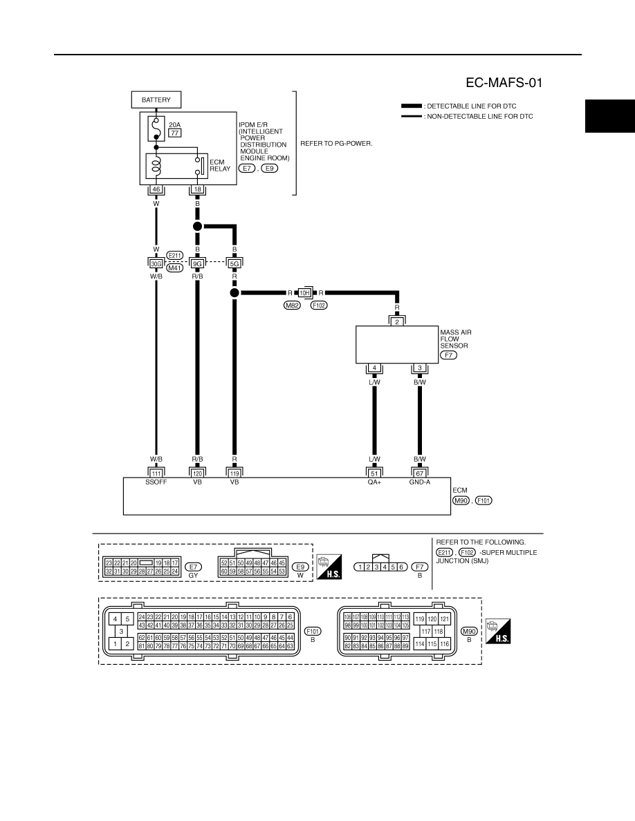
Wiring Diagram
INFOID:0000000001326591
Specification data are reference values and are measured between each terminal and ground.
CAUTION:
Do not use ECM ground terminals when measuring input/output voltage. Doing so may result in dam-
age to the ECM's transistor. Use a ground other than ECM terminals, such as the ground.
TBWM1327E
EC-764
< SERVICE INFORMATION >
[VK45DE]
DTC P0101 MAF SENSOR
Diagnosis Procedure
INFOID:0000000001326592
1.
INSPECTION START
Which malfunction (A or B) is duplicated?
A or B
A
>> GO TO 3.
B
>> GO TO 2.
2.
CHECK INTAKE SYSTEM
Check the following for connection.
• Air duct
• Vacuum hoses
• Intake air passage between air duct and intake manifold
OK or NG
OK
>> GO TO 3.
NG
>> Reconnect the parts.
3.
CHECK GROUND CONNECTIONS
1.
Turn ignition switch OFF.
2.
Loosen and retighten three ground screws on the body.
Refer to
OK or NG
OK
>> GO TO 4.
NG
>> Repair or replace ground connections.
TER-
MI-
NAL
NO.
WIRE
COLOR
ITEM
CONDITION
DATA (DC Voltage)
51
L/W
Mass air flow sensor
[Engine is running]
• Warm-up condition
• Idle speed
1.0 - 1.3V
[Engine is running]
• Warm-up condition
• Engine speed: 2,500 rpm
1.6 - 2.0V
67
B/W
Sensor ground
[Engine is running]
• Warm-up condition
• Idle speed
Approximately 0V
111
W/B
ECM relay
(Self shut-off)
[Engine is running]
[Ignition switch: OFF]
• For a few seconds after turning ignition
switch OFF
0 - 1.5V
[Ignition switch: OFF]
• More than a few seconds after turning igni-
tion switch OFF
BATTERY VOLTAGE
(11 - 14V)
119
120
R
R/B
Power supply for ECM
[Ignition switch: ON]
BATTERY VOLTAGE
(11 - 14V)
PBIB2195E
Нет комментариевНе стесняйтесь поделиться с нами вашим ценным мнением.
Текст