Infiniti FX35 / FX45. Manual — part 453
IGNITION SIGNAL
EC-573
< SERVICE INFORMATION >
[VQ35DE]
C
D
E
F
G
H
I
J
K
L
M
A
EC
N
P
O
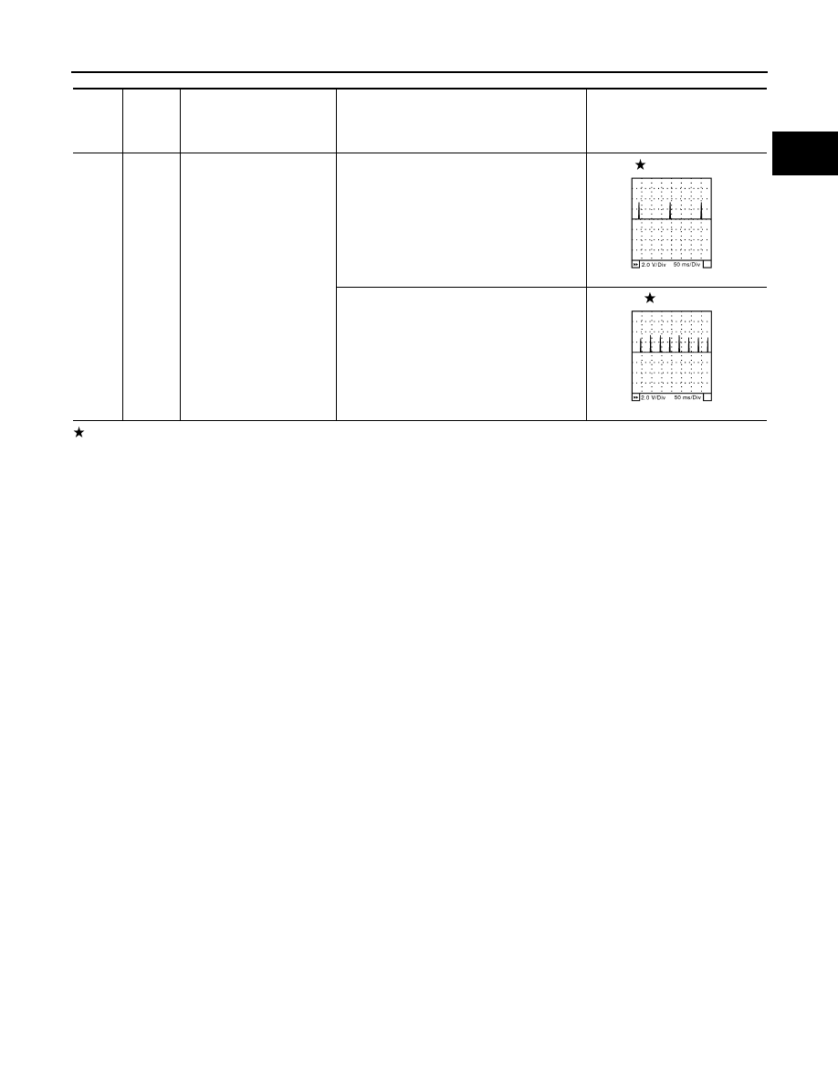
: Average voltage for pulse signal (Actual pulse signal can be confirmed by oscilloscope.)
TER-
MI-
NAL
NO.
WIRE
COLOR
ITEM
CONDITION
DATA (DC Voltage)
60
61
62
PU
L
Y
Ignition signal No. 5
Ignition signal No. 3
Ignition signal No. 1
[Engine is running]
• Warm-up condition
• Idle speed
NOTE:
The pulse cycle changes depending on rpm
at idle
0 - 0.2V
[Engine is running]
• Warm-up condition
• Engine speed: 2,500 rpm
0.1 - 0.4V
SEC986C
SEC987C
EC-574
< SERVICE INFORMATION >
[VQ35DE]
IGNITION SIGNAL
Specification data are reference values and are measured between each terminal and ground.
Pulse signal is measured by CONSULT-III.
CAUTION:
Do not use ECM ground terminals when measuring input/output voltage. Doing so may result in dam-
age to the ECM's transistor. Use a ground other than ECM terminals, such as the ground.
TBWM0736E
IGNITION SIGNAL
EC-575
< SERVICE INFORMATION >
[VQ35DE]
C
D
E
F
G
H
I
J
K
L
M
A
EC
N
P
O
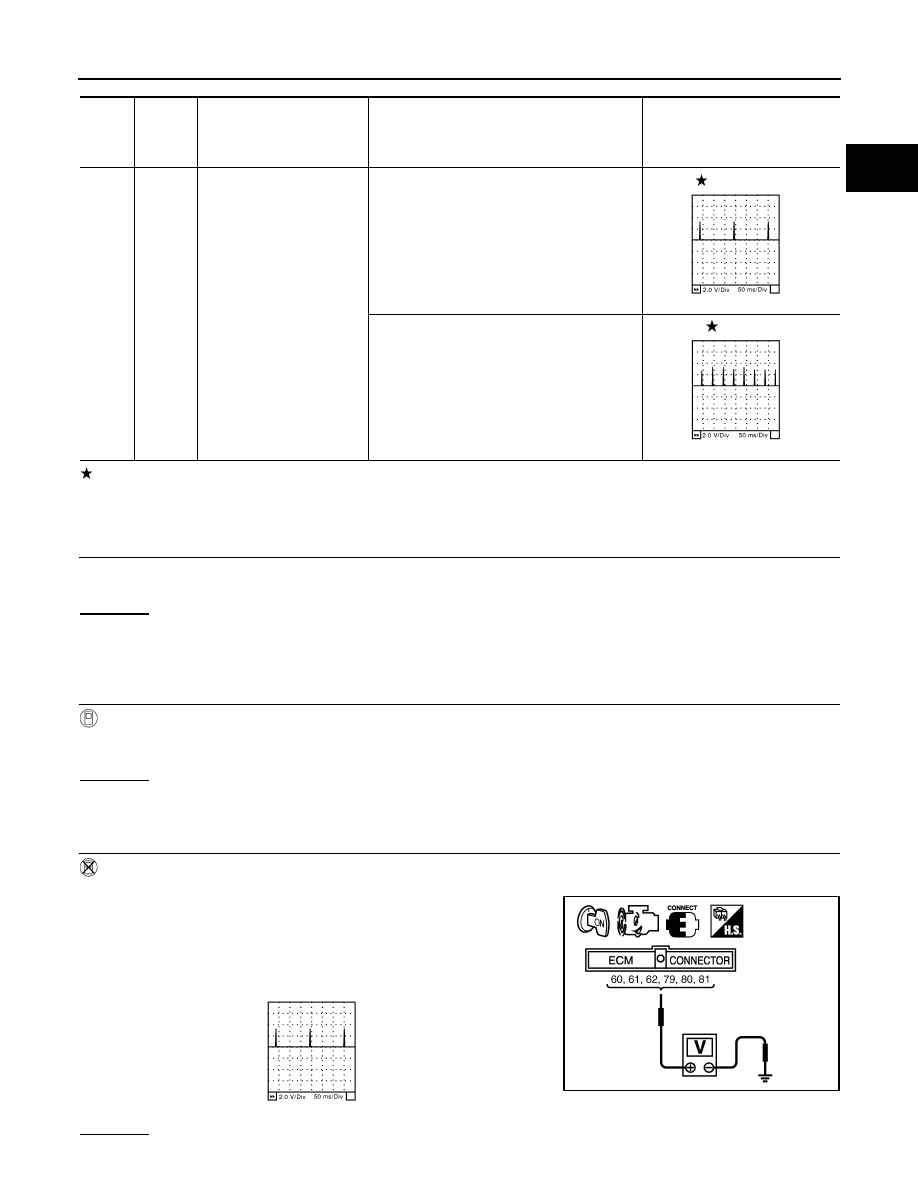
: Average voltage for pulse signal (Actual pulse signal can be confirmed by oscilloscope.)
Diagnosis Procedure
INFOID:0000000001326457
1.
CHECK ENGINE START
Turn ignition switch OFF, and restart engine.
Is engine running?
Yes or No
Yes (With CONSULT-III)>>GO TO 2.
Yes (Without CONSULT-III)>>GO TO 3.
No
>> GO TO 4.
2.
CHECK OVERALL FUNCTION
With CONSULT-III
1.
Perform “POWER BALANCE” in “ACTIVE TEST” mode with CONSULT-III.
2.
Make sure that each circuit produces a momentary engine speed drop.
OK or NG
OK
>> INSPECTION END
NG
>> GO TO 10.
3.
CHECK OVERALL FUNCTION
Without CONSULT-III
1.
Let engine idle.
2.
Read the voltage signal between ECM terminals 60, 61, 62, 79,
80, 81 and ground with an oscilloscope.
3.
Verify that the oscilloscope screen shows the signal wave as
shown below.
NOTE:
The pulse cycle changes depending on rpm at idle.
OK or NG
TER-
MI-
NAL
NO.
WIRE
COLOR
ITEM
CONDITION
DATA (DC Voltage)
79
80
81
SB
GY
OR
Ignition signal No. 6
Ignition signal No. 4
Ignition signal No. 2
[Engine is running]
• Warm-up condition
• Idle speed
NOTE:
The pulse cycle changes depending on rpm
at idle
0 - 0.2V
[Engine is running]
• Warm-up condition
• Engine speed: 2,500 rpm
0.1 - 0.4V
SEC986C
SEC987C
PBIB1186E
SEC986C

EC-576
< SERVICE INFORMATION >
[VQ35DE]
IGNITION SIGNAL
OK
>> INSPECTION END
NG
>> GO TO 10.
4.
CHECK IGNITION COIL POWER SUPPLY CIRCUIT-I
1.
Turn ignition switch OFF, wait at least 10 seconds and then turn ON.
2.
Check voltage between ECM terminals 119, 120 and ground
with CONSULT-III or tester.
OK or NG
OK
>> GO TO 5.
NG
>> Go to
.
5.
CHECK IGNITION COIL POWER SUPPLY CIRCUIT-II
1.
Turn ignition switch OFF.
2.
Disconnect condenser harness connector.
3.
Turn ignition switch ON.
4.
Check voltage between condenser terminal 1 and ground with
CONSULT-III or tester.
OK or NG
OK
>> GO TO 8.
NG
>> GO TO 6.
6.
CHECK IGNITION COIL POWER SUPPLY CIRCUIT-III
1.
Turn ignition switch OFF.
2.
Disconnect IPDM E/R harness connector E7.
3.
Check harness continuity between IPDM E/R terminal 17 and condenser terminal 1.
Refer to Wiring Diagram.
4.
Also check harness for short to ground and short to power.
OK or NG
OK
>> GO TO 17.
NG
>> GO TO 7.
7.
DETECT MALFUNCTIONING PART
Check the following.
• Harness connectors E64, F65
Voltage: Battery voltage
MBIB0034E
PBIB1606E
Voltage: Battery voltage
PBIB0624E
Continuity should exist.
Нет комментариевНе стесняйтесь поделиться с нами вашим ценным мнением.
Текст