Infiniti FX35 / FX45. Manual — part 798
TURN SIGNAL AND HAZARD WARNING LAMPS
LT-87
< SERVICE INFORMATION >
C
D
E
F
G
H
I
J
L
M
A
B
LT
N
O
P
5
PU
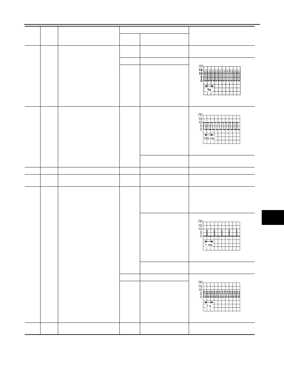
Turn signal lamp RH signal
ON
Turn signal switch OFF,
hazard switch OFF
Approx. 0 V
ON
Turn signal switch RH
Approx. 6.0 V
—
Hazard switch ON
6
SB
Warning output signal
ON
When turn signal lamp op-
erates normally
Approx. 5.0 V
Except when turn signal
lamp operates normally
Approx. 9.9 V
7
B
Ground
ON
—
Approx. 0 V
8
Y
Rear combination lamp RH
ground
ON
—
Approx. 0 V
9
LG
Rear combination lamp drive sig-
nal (RH)
—
Lighting switch OFF,
brake pedal released
(stop lamp switch OFF),
turn signal switch OFF,
hazard switch OFF
Approx. 0 V
Lighting switch 1ST
Approx. 0.3 V
Brake pedal depressed
(stop lamp switch ON)
Battery voltage
ON
Turn signal switch RH
Approx. 3.7 V
—
Hazard switch ON
10
BR
Rear combination lamp LH
ground
ON
—
Approx. 0 V
Termi-
nal
No.
Wire
color
Signal name
Measuring condition
Reference value
Ignition
switch
Operation or condition
PKIC6370E
PKIC9669E
PKIC9670E
PKIC9671E

LT-88
< SERVICE INFORMATION >
TURN SIGNAL AND HAZARD WARNING LAMPS
How to Proceed with Trouble Diagnosis
INFOID:0000000001328351
1.
Confirm the symptom or customer complaint.
2.
Understand operation description and function description. Refer to
.
3.
Perform preliminary check. Refer to
.
4.
Check symptom and repair or replace the cause of malfunction.
5.
Do turn signal and hazard warning lamps operate normally? If YES, GO TO 6. If NO, GO TO 4.
6.
INSPECTION END
Preliminary Check
INFOID:0000000001328352
CHECK POWER SUPPLY AND GROUND CIRCUIT
1.
CHECK FUSES
Check for blown fuses.
Refer to
LT-82, "Wiring Diagram - TURN -"
.
OK or NG
OK
>> GO TO 2.
NG
>> If fuse is blown, be sure to eliminate cause of malfunction before installing new fuse. Refer to
11
W
Rear combination lamp drive sig-
nal (LH)
—
Lighting switch OFF,
brake pedal released
(stop lamp switch OFF),
turn signal switch OFF,
hazard switch OFF
Approx. 0 V
Lighting switch 1ST
Approx. 0.3 V
Brake pedal depressed
(stop lamp switch ON)
Battery voltage
ON
Turn signal switch LH
Approx. 3.7 V
—
Hazard switch ON
Termi-
nal
No.
Wire
color
Signal name
Measuring condition
Reference value
Ignition
switch
Operation or condition
PKIC9670E
PKIC9671E
Unit
Power source
Fuse and fusible link No.
BCM
Battery
M
22
Ignition switch ON or START position
1
Ignition switch ACC or ON position
6
Rear combination lamp control unit
Battery
20
TURN SIGNAL AND HAZARD WARNING LAMPS
LT-89
< SERVICE INFORMATION >
C
D
E
F
G
H
I
J
L
M
A
B
LT
N
O
P
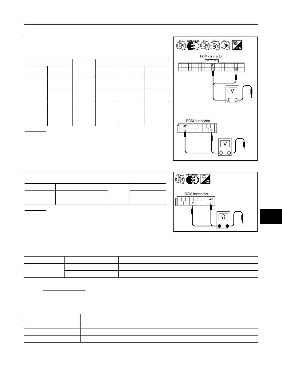
2.
CHECK POWER SUPPLY CIRCUIT
1.
Turn ignition switch OFF.
2.
Disconnect BCM connector.
3.
Check voltage between BCM harness connector and ground.
OK or NG
OK
>> GO TO 3.
NG
>> Repair harness or connector.
3.
CHECK GROUND CIRCUIT
Check continuity between BCM harness connector and ground.
OK or NG
OK
>> INSPECTION END
NG
>> Repair harness or connector.
CONSULT-III Functions (BCM)
INFOID:0000000001328353
CONSULT-III can display each diagnostic item using the diagnostic test mode shown following.
CONSULT-III BASIC OPERATION
.
DATA MONITOR
Display Item List
(+)
(-)
Ignition switch position
OFF
ACC
ON
BCM con-
nector
Terminal
M3
11
Ground
Approx. 0 V
Battery
voltage
Battery
voltage
38
Approx. 0 V
Approx. 0 V
Battery
voltage
M4
42
Battery
voltage
Battery
voltage
Battery
voltage
55
Battery
voltage
Battery
voltage
Battery
voltage
PKIA5204E
BCM connector
Terminal
Ground
Continuity
M4
49
Yes
52
SKIA5294E
BCM diagnosis part
Diagnosis mode
Description
FLASHER
DATA MONITOR
Displays BCM input data in real time.
ACTIVE TEST
Operation of electrical loads can be checked by sending driving signal to them.
Monitor item
Contents
IGN ON SW
“ON/OFF”
Displays “IGN position (ON)/OFF, ACC position (OFF)” judged from ignition switch signal.
HAZARD SW
“ON/OFF”
Displays “Hazard ON (ON)/Hazard OFF (OFF)” status, determined from hazard switch signal.
TURN SIGNAL R
“ON/OFF”
Displays “Turn right (ON)/Other (OFF)” status, determined from lighting switch signal.

LT-90
< SERVICE INFORMATION >
TURN SIGNAL AND HAZARD WARNING LAMPS
ACTIVE TEST
Display Item List
Turn Signal Lamp Does Not Operate
INFOID:0000000001381753
1.
CHECK BULB
Check bulb standard of each turn signal lamp is correct.
OK or NG
OK
>> GO TO 2.
NG
>> Replace turn signal lamp bulb.
2.
CHECK COMBINATION SWITCH INPUT SIGNAL
CONSULT-III DATA MONITOR
1.
Select “TURN SIGNAL R” and “TURN SIGNAL L” of BCM (FLASHER) data monitor item.
2.
With operating the test item, check the monitor status.
CHECK THE COMBINATION SWITCH
LT-104, "Combination Switch Inspection"
OK or NG
OK
>> GO TO 3.
NG
>> Check combination switch (lighting switch). Refer to
LT-104, "Combination Switch Inspection"
3.
ACTIVE TEST
CONSULT-III ACTIVE TEST
1.
Select “FLASHER” of BCM (FLASHER) active test item.
2.
With operating the test item, check the turn signal lamp operation.
GO TO 4
OK or NG
OK
>> Replace BCM. Refer to
BCS-13, "Removal and Installation of BCM"
.
NG
>> GO TO 4.
4.
CHECK TURN SIGNAL LAMP CIRCUIT
1.
Turn ignition switch OFF.
2.
Disconnect BCM connector, front combination lamp (RH and LH) connectors, side turn signal lamp (RH
and LH) connectors and rear combination lamp (RH and LH) connectors.
TURN SIGNAL L
“ON/OFF”
Displays “Turn left (ON)/Other (OFF)” status, determined from lighting switch signal.
BRAKE SW
“ON/OFF”
Displays “Stop lamp switch ON (ON)/Stop lamp switch OFF (OFF)” status, determined from stop lamp
switch signal.
Monitor item
Contents
Test item
Description
FLASHER
Turn signal lamp (right or left) can be operated by any ON-OFF operations.
When lighting switch is
TURN RH position
: TURN SIGNAL R ON
When lighting switch is
TURN LH position
: TURN SIGNAL L ON
Turn signal lamp should operate.
Нет комментариевНе стесняйтесь поделиться с нами вашим ценным мнением.
Текст