Infiniti FX35 / FX45. Manual — part 574
DTC P1564 ASCD STEERING SWITCH
EC-1057
< SERVICE INFORMATION >
[VK45DE]
C
D
E
F
G
H
I
J
K
L
M
A
EC
N
P
O
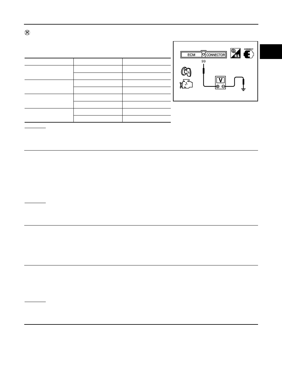
Without CONSULT-III
1.
Turn ignition switch ON.
2.
Check voltage between ECM terminal 99 and ground with press-
ing each button.
OK or NG
OK
>> GO TO 8.
NG
>> GO TO 3.
3.
CHECK ASCD STEERING SWITCH GROUND CIRCUIT FOR OPEN AND SHORT
1.
Turn ignition switch OFF.
2.
Disconnect ECM harness connector.
3.
Disconnect combination switch harness connector M203.
4.
Check harness continuity between combination switch terminal 15 and ECM terminal 82.
Refer to Wiring Diagram.
5.
Also check harness for short to ground and short to power.
OK or NG
OK
>> GO TO 5.
NG
>> GO TO 4.
4.
DETECT MALFUNCTIONING PART
Check the following.
• Combination switch (spiral cable)
• Harness for open and short between ECM and combination switch
>> Repair open circuit or short to ground or short to power in harness or connectors.
5.
CHECK ASCD STEERING SWITCH INPUT SIGNAL CIRCUIT FOR OPEN AND SHORT
1.
Check harness continuity between ECM terminal 99 and combination switch terminal 14.
Refer to Wiring Diagram.
2.
Also check harness for short to ground and short to power.
OK or NG
OK
>> GO TO 7.
NG
>> GO TO 6.
6.
DETECT MALFUNCTIONING PART
Check the following.
• Combination switch (spiral cable)
• Harness for open and short between ECM and combination switch
Switch
Condition
Voltage [V]
MAIN switch
Pressed
Approx. 0
Released
Approx. 4
CANCEL switch
Pressed
Approx. 1
Released
Approx. 4
RESUME/ACCELERATE
switch
Pressed
Approx. 3
Released
Approx. 4
SET/COAST switch
Pressed
Approx. 2
Released
Approx. 4
PBIB0311E
Continuity should exist.
Continuity should exist.
EC-1058
< SERVICE INFORMATION >
[VK45DE]
DTC P1564 ASCD STEERING SWITCH
>> Repair open circuit or short to ground or short to power in harness or connectors.
7.
CHECK ASCD STEERING SWITCH
EC-1058, "Component Inspection"
.
OK or NG
OK
>> GO TO 8.
NG
>> Replace ASCD steering switch.
8.
CHECK INTERMITTENT INCIDENT
>> INSPECTION END
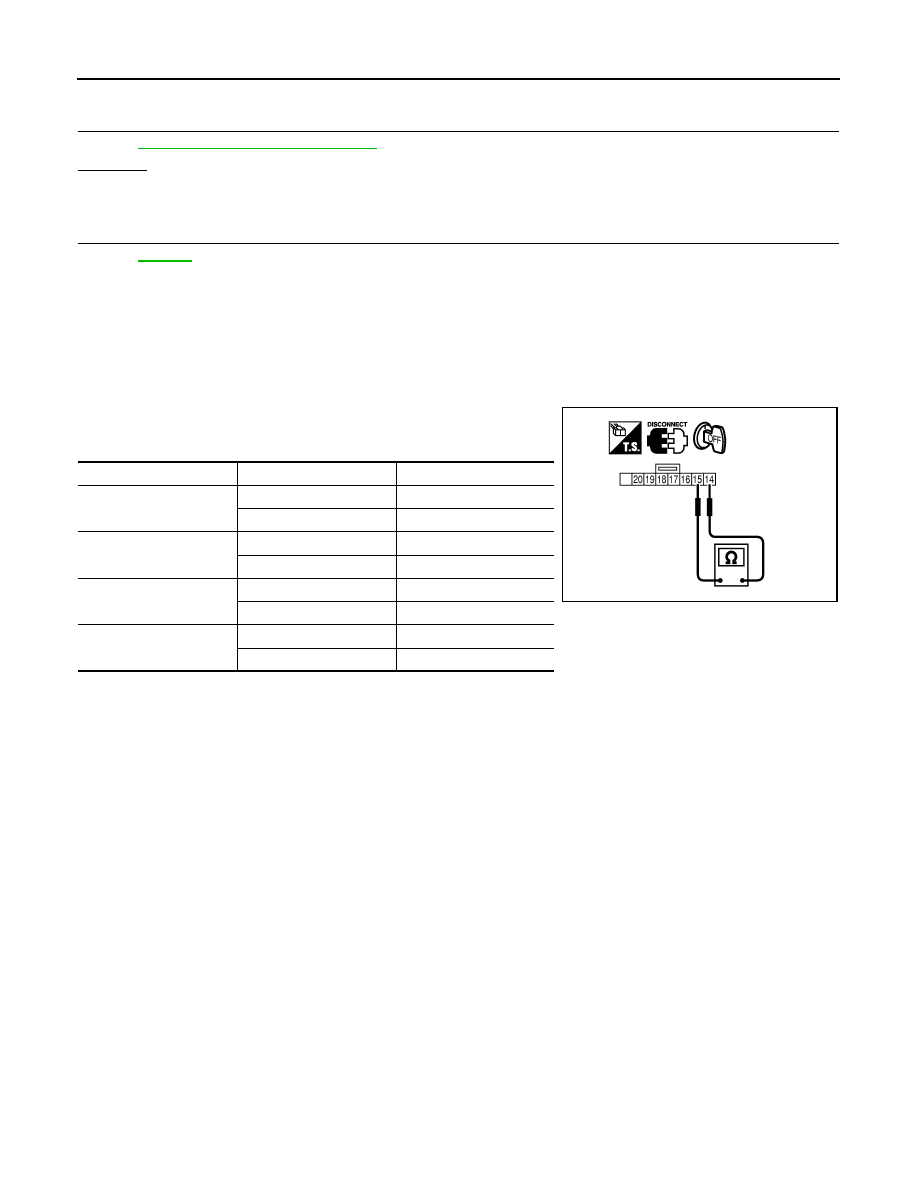
Component Inspection
INFOID:0000000001326931
ASCD STEERING SWITCH
1.
Disconnect combination switch (spiral cable) harness connector M203.
2.
Check continuity between combination switch terminals 14 and
15 with pushing each switch.
If NG, replace ASCD steering switch.
Switch
Condition
Resistance [
Ω
]
MAIN switch
Pressed
Approx. 0
Released
Approx. 4,000
CANCEL switch
Pressed
Approx. 250
Released
Approx. 4,000
RESUME/ACCELERATE
switch
Pressed
Approx. 1,480
Released
Approx. 4,000
SET/COAST switch
Pressed
Approx. 660
Released
Approx. 4,000
PBIB0967E

DTC P1568 ICC FUNCTION
EC-1059
< SERVICE INFORMATION >
[VK45DE]
C
D
E
F
G
H
I
J
K
L
M
A
EC
N
P
O
DTC P1568 ICC FUNCTION
On Board Diagnosis Logic
INFOID:0000000001326932
This self-diagnosis has the one trip detection logic.
The MIL will not light up for this diagnosis.
NOTE:
• If DTC P1568 is displayed with DTC U1000 or U1001, first perform the trouble diagnosis for DTC
U1000, U1001. Refer to
• If DTC P1568 is displayed with DTC U1010, first perform the trouble diagnosis for DTC U1010. Refer
.
• If DTC P1568 is displayed with DTC P0605, first perform the trouble diagnosis for DTC P0605. Refer
DTC Confirmation Procedure
INFOID:0000000001326933
CAUTION:
Always drive vehicle at a safe speed.
NOTE:
If DTC Confirmation Procedure has been previously conducted, always turn ignition switch OFF and wait at
least 10 seconds before conducting the next test.
TESTING CONDITION:
Step 4 may be conducted with the drive wheels lifted in the shop or by driving the vehicle. If a road test
is expected to be easier, it is unnecessary to lift the vehicle.
1.
Turn ignition switch ON.
2.
Press MAIN switch on ICC steering switch.
3.
Drive the vehicle at more than 40 km/h (25 MPH).
4.
Press SET/COAST switch.
5.
Check DTC.
6.
If DTC is detected, go to
EC-1059, "Diagnosis Procedure"
.
Diagnosis Procedure
INFOID:0000000001326934
1.
REPLACE ICC UNIT
1.
Replace ICC unit.
2.
3.
Check DTC of ICC unit. Refer to
.
>> INSPECTION END
DTC No.
Trouble Diagnosis
Name
DTC Detecting Condition
Possible Cause
P1568
1568
ICC function
ECM detects a difference between signals
from ICC unit is out of specified range.
• Harness or connectors
(The CAN communication line is open or
shorted.)
• ICC unit
• ECM
EC-1060
< SERVICE INFORMATION >
[VK45DE]
DTC P1572 ICC BRAKE SWITCH
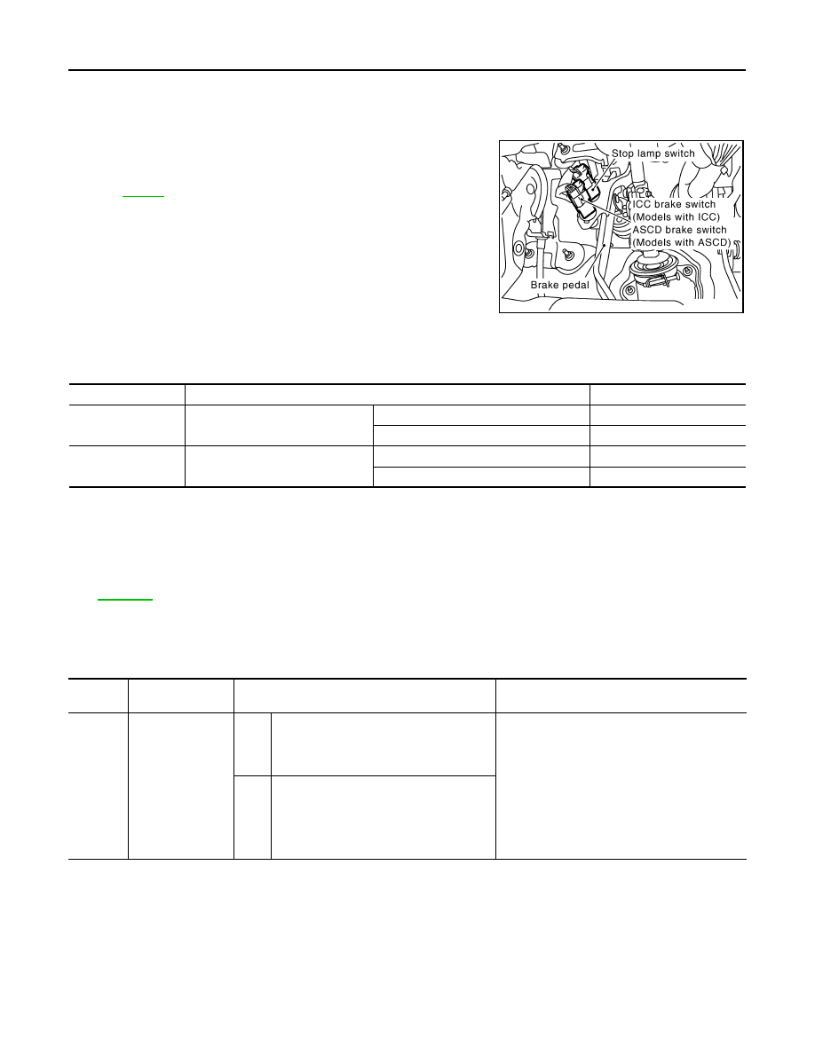
DTC P1572 ICC BRAKE SWITCH
Component Description
INFOID:0000000001326935
When the brake pedal is depressed, ICC brake switch is turned OFF
and stop lamp switch is turned ON. ECM detects the state of the
brake pedal by this input of two kinds (ON/OFF signal).
Refer to
CONSULT-III Reference Value in Data Monitor Mode
INFOID:0000000001326936
Specification data are reference values.
On Board Diagnosis Logic
INFOID:0000000001326937
This diagnosis has the one trip detection logic.
The MIL will not light up for this diagnosis.
NOTE:
• If DTC P1572 is displayed with DTC P0605, first perform the trouble diagnosis for DTC P0605. Refer
.
• This self-diagnosis has the one trip detection logic. When malfunction A is detected, DTC is not
stored in ECM memory. And in that case, 1st trip DTC and 1st trip freeze frame data are displayed.
1st trip DTC is erased when ignition switch OFF. And even when malfunction A is detected in two
consecutive trips, DTC is not stored in ECM memory.
DTC Confirmation Procedure
INFOID:0000000001326938
CAUTION:
Always drive vehicle at a safe speed.
NOTE:
• If DTC Confirmation Procedure has been previously conducted, always turn ignition switch OFF and wait at
least 10 seconds before conducting the next test.
PBIB2558E
MONITOR ITEM
CONDITION
SPECIFICATION
BRAKE SW1
(ICC brake switch)
• Ignition switch: ON
Brake pedal: Fully released
ON
Brake pedal: Slightly depressed
OFF
BRAKE SW2
(Stop lamp switch)
• Ignition switch: ON
Brake pedal: Fully released
OFF
Brake pedal: Slightly depressed
ON
DTC No.
Trouble diagnosis
name
DTC detecting condition
Possible cause
P1572
1572
ICC brake switch
A)
When the vehicle speed is above 30 km/h
(19 MPH), ON signals from the stop lamp
switch and the ICC brake switch are sent to
ECM at the same time.
• Harness or connectors
(The stop lamp switch circuit is shorted.)
• Harness or connectors
(The ICC brake switch circuit is shorted.)
• Stop lamp switch
• ICC brake switch
• ICC brake hold relay
• Incorrect stop lamp switch installation
• Incorrect ICC brake switch installation
• ECM
B)
ICC brake switch signal is not sent to ECM
for extremely long time while the vehicle is
driving
Нет комментариевНе стесняйтесь поделиться с нами вашим ценным мнением.
Текст