Infiniti FX35 / FX45. Manual — part 28
AT-40
< SERVICE INFORMATION >
ON BOARD DIAGNOSTIC (OBD) SYSTEM
Malfunction Indicator Lamp (MIL)
INFOID:0000000001327147
DESCRIPTION
The MIL is located on the instrument panel.
1.
The MIL will light up when the ignition switch is turned ON with-
out the engine running. This is a bulb check.
• If the MIL does not light up, refer to
, or see
VQ35DE) or
(for VK45DE).
2.
When the engine is started, the MIL should go off.
If the MIL remains on, the on board diagnostic system has
detected an engine system malfunction.
SEF217U

TROUBLE DIAGNOSIS
AT-41
< SERVICE INFORMATION >
D
E
F
G
H
I
J
K
L
M
A
B
AT
N
O
P
TROUBLE DIAGNOSIS
DTC Inspection Priority Chart
INFOID:0000000001327148
If some DTCs are displayed at the same time, perform inspections one by one based on the following priority
chart.
NOTE:
If “DTC U1000” is displayed with other DTCs, first perform the trouble diagnosis for “DTC U1000 CAN
COMMUNICATION”. Refer to
Fail-Safe
INFOID:0000000001327149
The TCM has an electrical fail-safe mode. This mode makes it possible to operate even if there is an error in a
main electronic control input/output signal circuit.
In fail-safe mode, even if the selector lever is “D” or “M” mode, the transmission is fixed in 2nd, 4th or 5th
(depending on the breakdown position), so the customer should feel “slipping” or “poor acceleration”.
Even when the electronic circuits are normal, under special conditions (for example, when slamming on the
brake with the wheels spinning drastically and stopping the tire rotation), the transmission can go into fail-safe
mode. If this happens, switch OFF the ignition switch for 10 seconds, then switch it ON again to return to the
normal shift pattern. Therefore, the customer's vehicle has returned to normal, so handle according to the
“WORK FLOW” (Refer to
FAIL-SAFE FUNCTION
If any malfunction occurs in a sensor or solenoid, this function controls the A/T to mark driving possible.
Vehicle Speed Sensor
Signals are input from two systems - from vehicle speed sensor A/T (revolution sensor) installed on the trans-
mission and from combination meter so normal driving is possible even if there is a malfunction in one of the
systems. And if vehicle speed sensor A/T (revolution sensor) has unusual cases, 5th gear and manual mode
are prohibited.
Accelerator Pedal Position Sensor
If there is a malfunction in one of the systems, the accelerator opening angle is controlled by ECM according
to a pre-determined accelerator angle to make driving possible. And if there are malfunctions in tow systems,
the engine speed is fixed by ECM to a pre-determined engine speed to make driving possible.
Throttle Position Sensor
If there is a malfunction in one of the systems, the accelerator opening angle is controlled by ECM according
to a pre-determined accelerator angle to make driving possible. And if there are malfunctions in tow systems,
the accelerator opening angle is controlled by the idle signal sent from the ECM which is based on input indi-
cating either idle condition or off-idle condition (pre-determined accelerator opening) in order to make driving
possible.
PNP Switch
In the unlikely event that a malfunction signal enters the TCM, the position indicator is switched OFF, the
starter relay is switched OFF (starter starting is disabled), the back-up lamp relay switched OFF (back-up lamp
is OFF) and the position is fixed to the “D” position to make driving possible.
Starter Relay
The starter relay is switched OFF. (Starter starting is disabled.)
A/T Interlock
• If there is an A/T interlock judgment malfunction, the A/T is fixed in 2nd gear to make driving possible.
NOTE:
When the vehicle is driven fixed in 2nd gear, a turbine revolution sensor malfunction is displayed,
but this is not a turbine revolution sensor malfunction.
• When the coupling pattern below is detected, the fail-safe action corresponding to the pattern is performed.
A/T 1st Engine Braking
Priority
Detected items (DTC)
1
U1000 CAN communication line
2
Except above
AT-42
< SERVICE INFORMATION >
TROUBLE DIAGNOSIS
When there is an A/T first gear engine brake judgment malfunction, the low coast brake solenoid is switched
OFF to avoid the engine brake operation.
Line Pressure Solenoid
The solenoid is switched OFF and the line pressure is set to the maximum hydraulic pressure to make driving
possible.
Torque Converter Clutch Solenoid
The solenoid is switched OFF to release the lock-up.
Low Coast Brake Solenoid
When a malfunction (electrical or functional) occurs, in order to make driving possible, if the solenoid is ON,
the transmission is held in 2nd gear; if the solenoid is OFF, the A/T is held in 4th gear. (Engine brake is not
applied in 1st and 2nd gear.)
Input Clutch Solenoid
If a malfunction (electrical or functional) occurs with the solenoid either ON or OFF, the A/T is held in 4th gear
to make driving possible.
Direct Clutch Solenoid
If a malfunction (electrical or functional) occurs with the solenoid either ON or OFF, the A/T is held in 4th gear
to make driving possible.
Front Brake Solenoid
If a malfunction (electrical or functional) occurs with the solenoid ON, in order to make driving possible, the A/
T is held in 5th gear; if the solenoid is OFF, 4th gear.
High and Low Reverse Clutch Solenoid
If a malfunction (electrical or functional) occurs with the solenoid either ON or OFF, the A/T is held in 4th gear
to make driving possible.
Turbine Revolution Sensor 1 or 2
The control is the same as if there were no turbine revolution sensors, 5th gear and manual mode are prohib-
ited.
How to Perform Trouble Diagnosis for Quick and Accurate Repair
INFOID:0000000001327150
INTRODUCTION
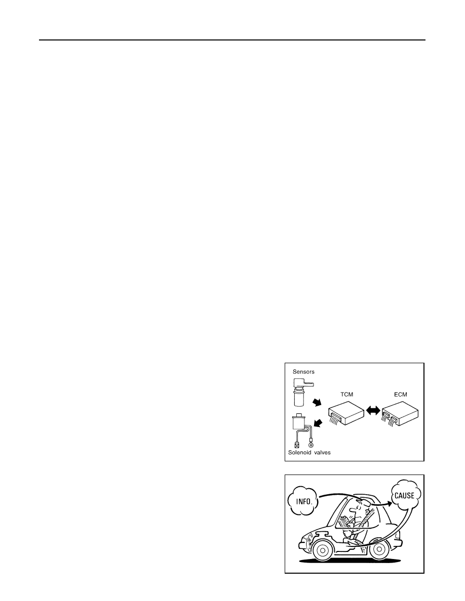
The TCM receives a signal from the vehicle speed sensor, accelerator pedal position sensor (throttle position
sensor) or PNP switch and provides shift control or lock-up control via A/T solenoid valves.
The TCM also communicates with the ECM by means of a signal
sent from sensing elements used with the OBD-related parts of the
A/T system for malfunction-diagnostic purposes. The TCM is capa-
ble of diagnosing malfunctioning parts while the ECM can store mal-
functions in its memory.
Input and output signals must always be correct and stable in the
operation of the A/T system. The A/T system must be in good oper-
ating condition and be free of valve seizure, solenoid valve malfunc-
tion, etc.
It is much more difficult to diagnose a error that occurs intermittently
rather than continuously. Most intermittent errors are caused by poor
electric connections or improper wiring. In this case, careful check-
ing of suspected circuits may help prevent the replacement of good
parts.
A visual check only may not find the cause of the errors. A road test
with CONSULT-III (or GST) or a circuit tester connected should be
performed. Follow the "WORK FLOW".
SAT631IB
SAT632I
TROUBLE DIAGNOSIS
AT-43
< SERVICE INFORMATION >
D
E
F
G
H
I
J
K
L
M
A
B
AT
N
O
P
Before undertaking actual checks, take a few minutes to talk with a
customer who approaches with a driveability complaint. The cus-
tomer can supply good information about such errors, especially
intermittent ones. Find out what symptoms are present and under
what conditions they occur. A “DIAGNOSTIC WORKSHEET” as
shown on the example (Refer to "Diagnostic Worksheet Chart")
should be used.
Start your diagnosis by looking for “conventional” errors first. This will
help troubleshoot driveability errors on an electronically controlled
engine vehicle.
Also check related Service bulletins.
WORK FLOW
A good understanding of the malfunction conditions can make troubleshooting faster and more accurate.
In general, each customer feels differently about a malfunction. It is important to fully understand the symp-
toms or conditions for a customer complaint.
Make good use of the two sheets provided, “Information from Customer” and “Diagnostic worksheet chart”, to
perform the best troubleshooting possible.
Work Flow Chart
SEF234G
Нет комментариевНе стесняйтесь поделиться с нами вашим ценным мнением.
Текст