Infiniti FX35, FX50 (S51). Manual — part 1054

EXL-212
< ECU DIAGNOSIS INFORMATION >
[XENON TYPE]
AFS CONTROL UNIT
Fail-Safe
INFOID:0000000005244780
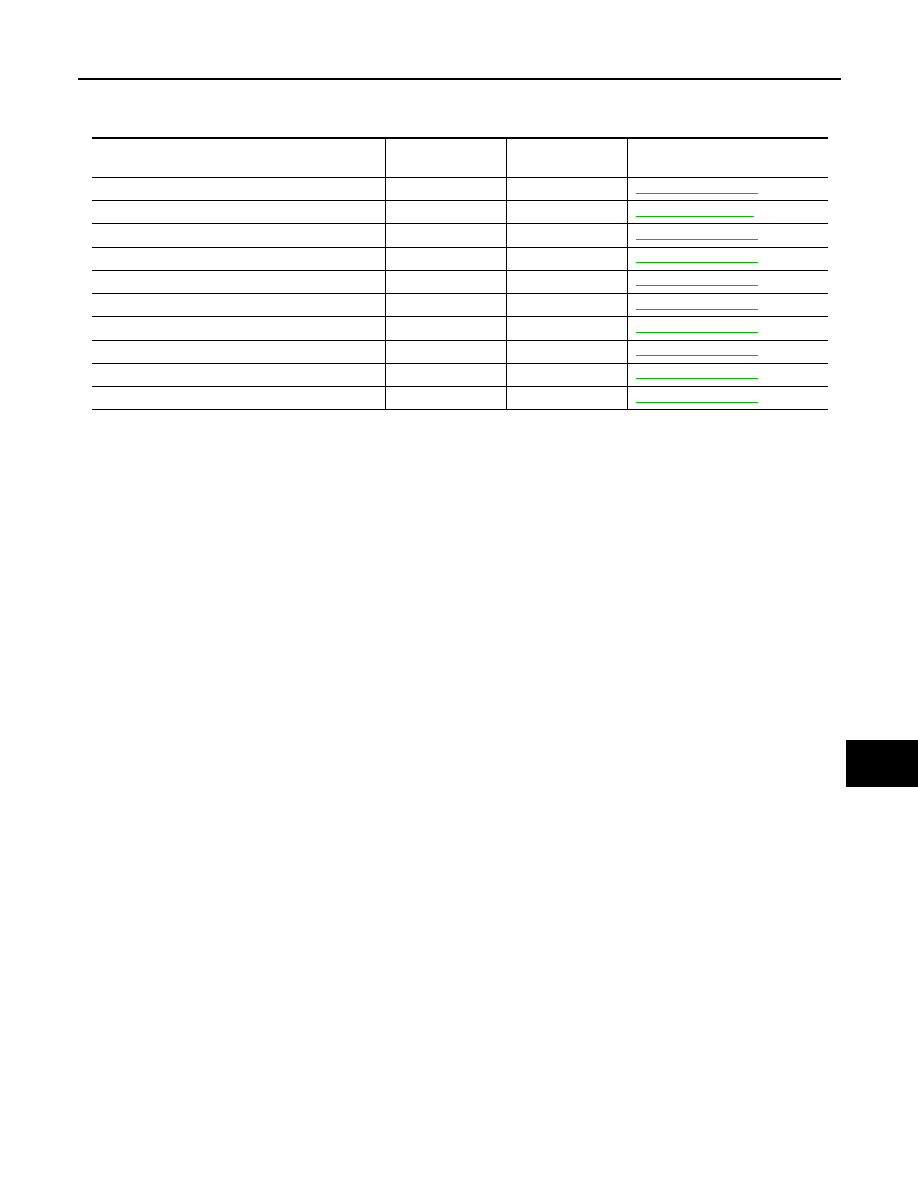
DTC Inspection Priority Chart
INFOID:0000000005244781
If some DTCs are displayed at the same time, perform inspections one by one based on the following priority
chart.
NOTE:
• If DTC U1000 is displayed with other DTC, first perform the trouble diagnosis for DTC U1000.
• If DTC U1010 is displayed with other DTC, first perform the trouble diagnosis for DTC U1010.
DTC
Fail-safe
AFS OFF indica-
tor lamp
Cancellation
CAN COMM CIRCUIT
[U1000]
• Right and left swivel motors stop at the position when
DTC is detected.
• Right and left aiming motors stop at the position when
DTC is detected.
Blinks 1 second
each.
Ignition switch OFF
CONTROL UNIT (CAN)
[U1010]
• Right and left swivel motors stop at the position when
DTC is detected.
• Right and left aiming motors stop at the position when
DTC is detected.
Blinks 1 second
each.
Ignition switch OFF
SWIVEL ACTUATOR
[RH, LH]
[B2503, B2504]
• Right and left swivel motors stop at the position when
DTC is detected.
• The signal, approximately 2 V decreased from the level-
izer signal when DTC detected, is output.
Blinks 1 second
each.
Ignition switch OFF
HI SEN UNUSUAL [RR]
[B2514]
• Right and left aiming motors stop at the position when
DTC is detected.
—
Ignition switch OFF
ST ANG SEN SIG
[C0126]
• Right and left swivel motor swivel angle returns to 0
°
and
fixed.
Blinks 1 second
each.
Ignition switch OFF
SHIFT SIG [P, R]
[B2516]
• Right and left swivel motor swivel angle returns to 0
°
and
fixed.
Blinks 1 second
each.
Ignition switch OFF
VEHICLE SPEED SIG
[B2517]
• Right and left swivel motor swivel angle returns to 0
°
and
fixed.
• Right and left aiming motors stop at the position when
DTC is detected.
Blinks 1 second
each.
Ignition switch OFF
LEVELIZER CALIB
[B2519]
• Right and left aiming motors stop at the position when
DTC is detected.
—
When the levelizer
adjustment is com-
pleted.
ST ANGLE SEN CALIB
[C0428]
• Right and left swivel motor swivel angle returns to 0
°
and
fixed.
Blinks 1 second
each.
When the steering
angle sensor neutral
position registration is
competed
ECU CIRC
[B2521]
• Right and left swivel motors stop at the position when
DTC is detected.
• Right and left aiming motors stop at the position when
DTC is detected.
Blinks 1 second
each.
Ignition switch OFF
Priority
Detected items (DTC)
1
• U1000 CAN COMM CIRCUIT
• U1010 CONTROL UNIT (CAN)
2
• B2519 LEVELIZER CALIB
• B2521 ECU CIRC
• C0428 ST ANG SEN CALIB
3
• B2503 SWIVEL ACTUATOR [RH]
• B2504 SWIVEL ACTUATOR [LH]
• B2514 HI SEN UNUSUAL [RR]
• B2516 SHIFT SIG [P, R]
• B2517 VEHICLE SPEED SIG
• C0126 ST ANG SEN SIG
AFS CONTROL UNIT
EXL-213
< ECU DIAGNOSIS INFORMATION >
[XENON TYPE]
C
D
E
F
G
H
I
J
K
M
A
B
EXL
N
O
P
DTC Index
INFOID:0000000005244782
×
: Applicable
CONSULT indication
Fail-safe
AFS OFF indicator
lamp
Reference
U1000: CAN COMM CIRCUIT
×
×
U1010: CONTROL UNIT (CAN)
×
×
B2503, B2504: SWIVEL ACTUATOR [RH, LH]
×
×
B2514: HI SEN UNUSUAL [RR]
×
B2516: SHIFT SIG [P, R]
×
×
B2517: VEHICLE SPEED SIG
×
×
B2519: LEVELIZER CALIB
×
B2521: ECU CIRC
×
×
C0126: ST ANG SEN SIG
×
×
C0428: ST ANGLE SEN CALIB
×
×

EXL-214
< SYMPTOM DIAGNOSIS >
[XENON TYPE]
EXTERIOR LIGHTING SYSTEM SYMPTOMS
SYMPTOM DIAGNOSIS
EXTERIOR LIGHTING SYSTEM SYMPTOMS
Symptom Table
INFOID:0000000005244783
CAUTION:
Perform the self-diagnosis with CONSULT-III before the symptom diagnosis. Perform the trouble diag-
nosis if any DTC is detected.
Symptom
Possible cause
Inspection item
Headlamp does not
switch to the high beam.
One side
• Fuse
• Harness between IPDM E/R
and the front combination lamp
• Front combination lamp
(High beam solenoid)
• IPDM E/R
Headlamp (HI) circuit
Refer to
.
Both sides
Symptom diagnosis
"BOTH SIDE HEADLAMPS DO NOT SWITCH TO HIGH BEAM"
Refer to
High beam indicator lamp is not turned ON.
(Headlamp switches to the high beam.)
• Combination meter
• Unified meter and A/C amp.
• Unified meter and A/C amp.
Data monitor "HI-BEAM IND"
• BCM (HEAD LAMP)
Active test "HEADLAMP"
Headlamp does not
switch to the low beam.
One side
Front combination lamp (High
beam solenoid)
—
Both sides
• Combination switch
• Harness between the combina-
tion switch and BCM
• BCM
Combination switch
Refer to
High beam request signal
• BCM
• IPDM E/R
IPDM E/R
Data monitor "HL HI REQ"
IPDM E/R
—
Headlamp is not turned
ON.
One side
• Fuse
• Xenon bulb
• Harness between IPDM E/R
and the front combination lamp
• Front combination lamp (xenon
headlamp)
• IPDM E/R
Headlamp (LO) circuit
Refer to
.
Both sides
Symptom diagnosis
"BOTH SIDE HEADLAMPS (LO) ARE NOT TURNED ON"
Refer to
Headlamp is not turned
OFF.
When the ignition
switch is turned ON
The ignition switch is
turned OFF (After acti-
vating the battery sav-
er.)
IPDM E/R
—
Headlamp is not turned ON/OFF with the lighting
switch AUTO.
• Combination switch
• Harness between the combina-
tion switch and BCM
• BCM
Combination switch
Refer to
• Optical sensor
• Harness between the optical
sensor and BCM
• BCM
Optical sensor
Refer to
.

EXTERIOR LIGHTING SYSTEM SYMPTOMS
EXL-215
< SYMPTOM DIAGNOSIS >
[XENON TYPE]
C
D
E
F
G
H
I
J
K
M
A
B
EXL
N
O
P
Front fog lamp is not
turned ON.
One side
• Front fog lamp bulb
• Harness between IPDM E/R
and the front fog lamp
• IPDM E/R
Front fog lamp circuit
Refer to
.
Both side
Symptom diagnosis
"BOTH SIDE FRONT FOG LAMPS ARE NOT TURNED ON"
Refer to
Front fog lamp is not turned ON.
Front fog lamp indicator lamp is not turned ON.
(Front fog lamp is turned ON.)
• Combination meter
• Unified meter and A/C amp.
• Unified meter and A/C amp.
Data monitor "FR FOG IND"
• BCM (HEAD LAMP)
Active test "FR FOG LAMP"
Parking lamp is not turned ON.
• Fuse
• Parking lamp bulb
• Harness between IPDM E/R
and the front combination lamp
• Front combination lamp
• IPDM E/R
Parking lamp circuit
Refer to
.
Tail lamp is not turned ON.
• Harness between IPDM E/R
and the rear combination lamp
• Rear combination lamp
Tail lamp circuit
Refer to
.
License plate lamp is not turned ON.
• Harness between IPDM E/R
and the license plate lamp
• License plate lamp
License plate lamp circuit
Refer to
.
Tail lamp and license plate lamp are not turned ON.
• Fuse
• Harness between IPDM E/R
and the rear combination lamp
• IPDM E/R
Tail lamp circuit
Refer to
.
• Parking lamp, side marker lamp, tail lamp and li-
cense plate lamp are not turned ON.
• Parking lamp, side marker lamp, tail lamp and li-
cense plate lamp are not turned OFF.
(Each illumination is turned ON/OFF.)
Symptom diagnosis
"PARKING, LICENSE PLATE AND TAIL LAMPS ARE NOT TURNED
ON"
Refer to
Tail lamp indicator lamp is not turned ON.
(Parking and tail lamps are turned ON.)
• Combination meter
• Unified meter and A/C amp.
• Unified meter and A/C amp.
Data monitor "LIGHT IND"
• BCM (HEAD LAMP)
Active test "TAIL LAMP"
Turn signal lamp does not
blink.
Indicator lamp is nor-
mal.
(The applicable side
performs the high flash-
er activation.)
• Harness between BCM and
each turn signal lamp
• Turn signal lamp bulb
Turn signal lamp circuit
Refer to
.
Indicator lamp is includ-
ed
• Combination switch
• Harness between the combina-
tion switch and BCM
• BCM
Combination switch
Refer to
.
Turn signal indicator lamp
does not blink.
(The turn signal indicator
lamp is normal.)
One side
Combination meter
—
Both sides
(Always)
• Turn signal indicator lamp sig-
nal
- Unified meter and A/C amp.
- BCM
• Combination meter
• Unified meter and A/C amp.
Data monitor "TURN IND"
• BCM (FLASHER)
Active test "FLASHER"
Both sides
(Only when activating
the hazard warning
lamp with the ignition
switch OFF.)
• The combination meter power
supply and the ground circuit
• Combination meter
Combination meter
Power supply and the ground circuit
Refer to
.
Symptom
Possible cause
Inspection item
Нет комментариевНе стесняйтесь поделиться с нами вашим ценным мнением.
Текст