Infiniti FX35, FX50 (S51). Manual — part 1758
ST-24
< REMOVAL AND INSTALLATION >
LOWER SHAFT
LOWER SHAFT
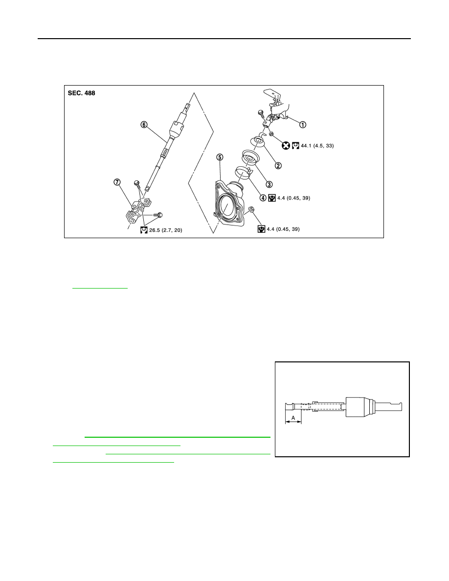
Exploded View
INFOID:0000000005235279
Removal and Installation
INFOID:0000000005235280
REMOVAL
1.
Set the vehicle to the straight-ahead position.
2.
Fix the steering wheel.
3.
Remove lower joint fixing bolt (steering gear side).
4.
Separate the lower shaft from the steering gear assembly by
sliding the slide shaft (A: sliding range).
CAUTION:
Spiral cable may be cut if steering wheel turns while sepa-
rating steering column assembly and steering gear assem-
bly. Be sure to secure steering wheel using string to avoid
turning.
5.
Remove the accelerator pedal bracket and lever assembly.
Refer to
ACC-3, "MODELS WITHOUT DISTANCE CONTROL
ASSIST SYSTEM : Exploded View"
(without distance control
assist system),
ACC-4, "MODELS WITH DISTANCE CONTROL
ASSIST SYSTEM : Exploded View"
(with distance control assist
system).
6.
Remove the parking brake wire clamp stay.
7.
Remove the hole cover mounting nuts.
8.
Remove the upper joint fixing bolt and nut (lower shaft side).
9.
Remove the lower shaft and hole cover.
10. Remove collar, hole cover seal, clamp and hole cover.
INSTALLATION
Note the following, and install in the reverse order of removal.
CAUTION:
1.
Steering column assembly
2.
Collar
3.
Hole cover seal
4.
Clamp
5.
Hole cover
6.
Lower shaft
7.
Lower joint
Refer to
for symbols in the figure.
JSGIA0357GB
JSGIA0035ZZ
LOWER SHAFT
ST-25
< REMOVAL AND INSTALLATION >
C
D
E
F
H
I
J
K
L
M
A
B
ST
N
O
P
Spiral cable may be cut if steering wheel turns while separating steering column assembly and steer-
ing gear assembly. Be sure to secure steering wheel using string to avoid turning.
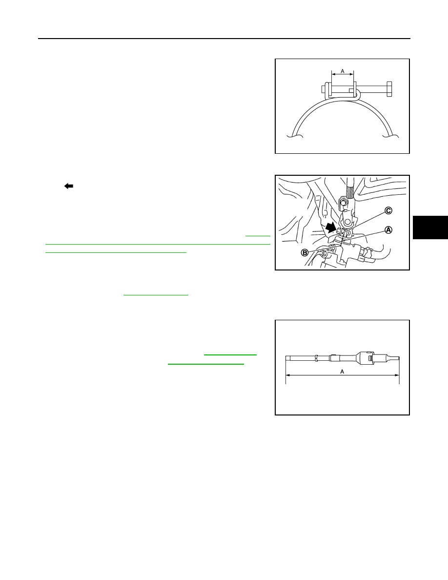
• Tighten the clamp to the specified torque and check the clamp
length (A).
• When installing lower joint to steering gear assembly, follow the
procedure listed below.
- Set rack of steering gear in the neutral position.
NOTE:
To get the neutral position of rack, turn gear-sub assembly and
measure the distance of inner socket, and then measure the inter-
mediate position of the distance.
- Align rear cover cap projection (A) with the marking position of
gear housing assembly (B).
- Install slit part of lower joint (C) aligning with the rear cover cap
projection (A). Make sure that the slit part of lower joint (C) is
aligned with rear cover cap projection (A) and the marking position
of gear housing assembly (B).
• Adjust neutral position of steering angle sensor. Refer to
"ADJUSTMENT OF STEERING ANGLE SENSOR NEUTRAL
POSITION : Special Repair Requirement"
• Check the following after installation:
- Check if steering wheel turns smoothly when it is turned several
times fully to the end of the left and right.
- Check the steering wheel play, neutral position steering wheel, steering wheel turning force, and front wheel
turning angle. Refer to
Inspection
INFOID:0000000005235281
• Check the length (A) (extended position) of the lower shaft.
• Check each part of lower shaft for damage or other malfunctions.
Replace if there are.
A
: 14.0 – 18.0 mm (0.551 – 0.709 in)
: Bolt
JSGIA0094ZZ
JSGIA0111ZZ
Standard
A
: Refer to
JSGIA0358ZZ

ST-26
< REMOVAL AND INSTALLATION >
STEERING GEAR AND LINKAGE
STEERING GEAR AND LINKAGE
Exploded View
INFOID:0000000005235282
REMOVAL
DISASSEMBLY
1.
Steering gear assembly
2.
Cotter pin
3.
Rack stay
: Vehicle front
Refer to
for symbols in the figure.
JSGIA0641GB
1.
Low pressure piping
2.
Rear cover cap
3.
Gear-sub assembly
4.
Power steering solenoid valve
5.
O-ring
6.
Adjusting screw
7.
Spring
8.
Retainer
9.
Outer socket
JSGIA0428GB
STEERING GEAR AND LINKAGE
ST-27
< REMOVAL AND INSTALLATION >
C
D
E
F
H
I
J
K
L
M
A
B
ST
N
O
P
Removal and Installation
INFOID:0000000005235283
REMOVAL
1.
Set the vehicle to the straight-ahead position.
2.
Remove tires with a power tool.
3.
Remove floor under cover. Refer to
.
4.
Remove front cross bar. Refer to
(AWD).
5.
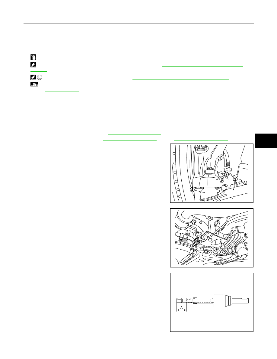
Remove cotter pin (1), and then loosen the nut.
6.
Remove steering outer socket (2) from steering knuckle (3) so
as not to damage ball joint boot (4) using a ball joint remover
(commercial service tool).
CAUTION:
Temporarily tighten the nut to prevent damage to threads
and to prevent the ball joint remover from suddenly coming
off.
7.
Remove high pressure piping and low pressure piping of
hydraulic piping, and then drain power steering fluid.
8.
Remove power steering solenoid valve harness connector (1)
and harness clip.
9.
Remove steering hydraulic piping bracket (VK50VE).
10. Remove rack stay. Refer to
.
11. Remove lower joint fixing bolt (steering gear side).
12. Separate the lower shaft from the steering gear assembly by
sliding the side shaft (A: sliding range).
CAUTION:
Spiral cable may be cut if steering wheel turns while sepa-
rating steering column assembly and steering gear assem-
bly. Be sure to secure steering wheel using string to avoid
turning.
13. Remove steering gear assembly.
INSTALLATION
Note the following, and install in the reverse order of removal.
10. Boot clamp
11.
Boot
12. Inner socket
13. Boot clamp (stainless wire)
14. Spacer
15. Cylinder tubes
16. Gear housing assembly
17. Rack oil seal
18. Rack assembly
19. Rack Teflon ring
20. End cover assembly
: Apply power steering fluid.
: Apply Genuine High Performance Thread Sealant or equivalent. Refer to
GI-16, "Recommended Chemical Products and
: Apply Genuine Silicone RTV or equivalent. Refer to
GI-16, "Recommended Chemical Products and Sealants"
: Apply multi-purpose grease.
Refer to
for symbols not described on the above.
PGIA0063E
JSGIA0360ZZ
JSGIA0035ZZ
Нет комментариевНе стесняйтесь поделиться с нами вашим ценным мнением.
Текст