Infiniti FX35, FX50 (S51). Manual — part 1878

TCM
TM-319
< ECU DIAGNOSIS INFORMATION >
[7AT: RE7R01B (VK50VE)]
C
E
F
G
H
I
J
K
L
M
A
B
TM
N
O
P
SHIFT IND SIGNAL
When the selector lever is positioned in between each po-
sition
OFF
Selector lever in “P” position
P
Selector lever in “R” position
R
Selector lever in “N” position
N
Selector lever in “D” position
D
Selector lever in “D” position: 7GR
Selector lever in “D” position: 6GR
6
Selector lever in “D” position: 5GR
5
Selector lever in “D” position: 4GR
4
Selector lever in “D” position: 3GR
3
Selector lever in “D” position: 2GR
2
Selector lever in “D” position: 1GR
1
Selector lever in “M” position: 1GR
M1
Selector lever in “M” position: 2GR
M2
Selector lever in “M” position: 3GR
M3
Selector lever in “M” position: 4GR
M4
Selector lever in “M” position: 5GR
M5
Selector lever in “M” position: 6GR
M6
Selector lever in “M” position: 7GR
M7
Driving with DS mode
DS
STARTER RELAY
Selector lever in “P” and “N” positions
ON
Other than the above
OFF
F-SAFE IND/L
For 2 seconds after the ignition switch is turned ON
ON
Other than the above
OFF
ATF WARN LAMP*
When TCM transmits the ATF indicator lamp signal
ON
Other than the above
OFF
MANU MODE IND
Driving with manual mode
ON
Other than the above
OFF
ON OFF SOL MON
Selector lever in “P” and “N” positions
ON
Driving with 1GR to 3GR
Other than the above
OFF
START RLY MON
Selector lever in “P” and “N” positions
ON
Other than the above
OFF
ON OFF SOL
Selector lever in “P” and “N” positions
ON
Driving with 1GR to 3GR
Other than the above
OFF
Item name
Condition
Value / Status (Approx.)
TM-320
< ECU DIAGNOSIS INFORMATION >
[7AT: RE7R01B (VK50VE)]
TCM
*: Not mounted but always display as OFF.
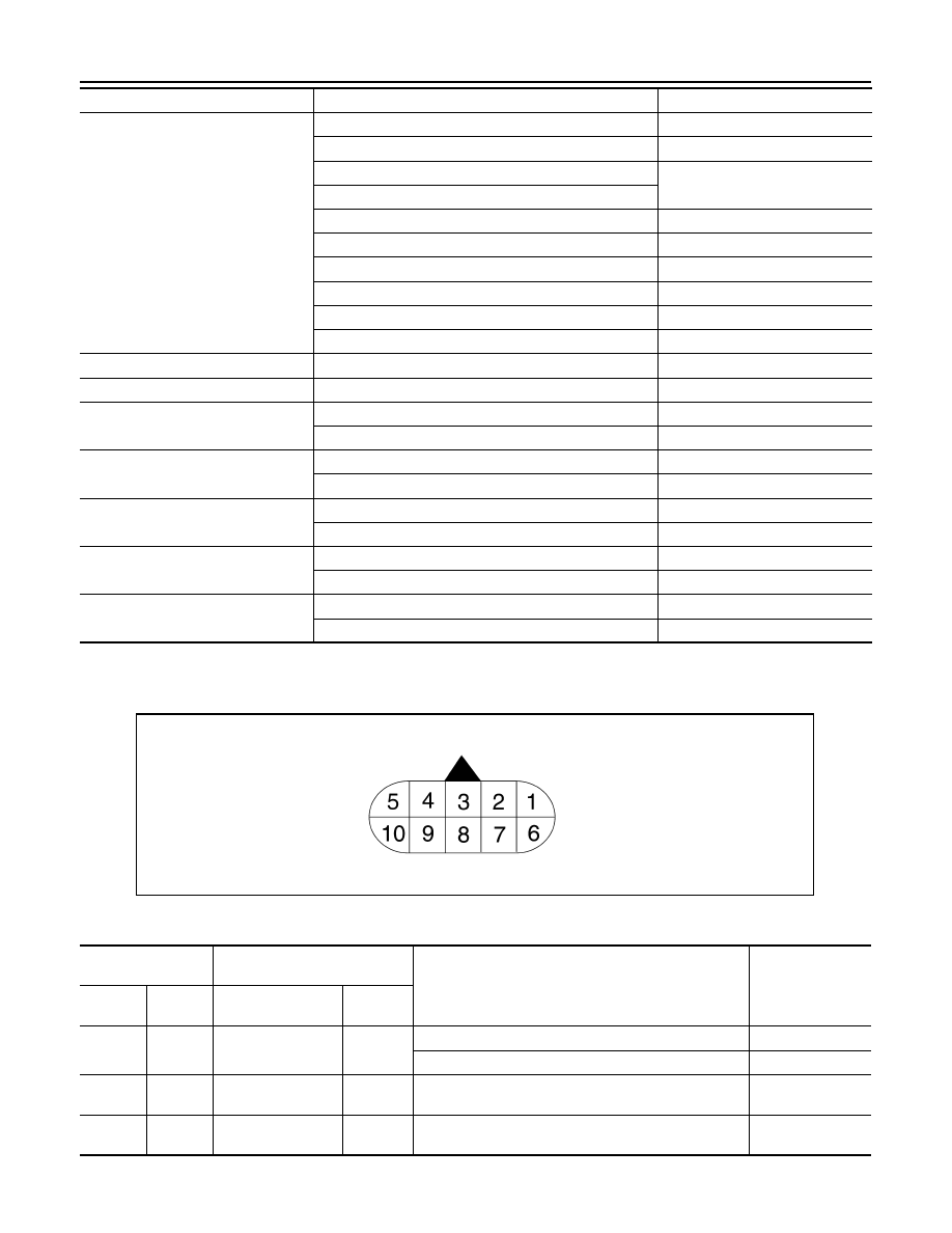
TERMINAL LAYOUT
PHYSICAL VALUES
SLCT LVR POSI
Selector lever in “N” and “P” positions
N/P
Selector lever in “R” position
R
Selector lever in “D” and “DS” positions
D
Selector lever in “M” position: 7GR
Selector lever in “M” position: 6GR
6
Selector lever in “M” position: 5GR
5
Selector lever in “M” position: 4GR
4
Selector lever in “M” position: 3GR
3
Selector lever in “M” position: 2GR
2
Selector lever in “M” position: 1GR
1
GEAR
During driving
1st, 2nd, 3rd, 4th, 5th, 6th, 7th
NEXT GR POSI
During driving
1st, 2nd, 3rd, 4th, 5th, 6th, 7th
SHIFT MODE
Driving with the D position
0 or 3
Driving with the manual mode
4 or 8
D/C PARTS
At 1 - 2 gear shift control
FAIL
Other than the above
NOTFAIL
FR/B PARTS
At control fixed to 1GR
FAIL
Other than the above
NOTFAIL
2346/B PARTS
At control fixed to 1GR
FAIL
Other than the above
NOTFAIL
2346B/DC PARTS
At 2 - 3 - 4 gear shift control
FAIL
Other than the above
NOTFAIL
Item name
Condition
Value / Status (Approx.)
SCIA1658E
Terminal
(Wire color)
Description
Condition
Value (Approx.)
+
−
Signal name
Input/
Output
1
(Y)
Ground
Power supply
Input
Ignition switch ON
Battery voltage
Ignition switch OFF
0 V
2
(R)
Ground
Power supply
(Memory back-up)
Input
Always
Battery voltage
3
(L)
—
CAN-H
Input/
Output
—
—
TCM
TM-321
< ECU DIAGNOSIS INFORMATION >
[7AT: RE7R01B (VK50VE)]
C
E
F
G
H
I
J
K
L
M
A
B
TM
N
O
P
4
(V)
—
K-line
Input/
Output
—
—
5
(B)
Ground
Ground
Output
Always
0 V
6
(Y)
Ground
Power supply
Input
Ignition switch ON
Battery voltage
Ignition switch OFF
0 V
7
(R)
Ground
Back-up lamp relay
Input
Ignition switch ON
Selector lever in “R” position.
0 V
Selector lever in other positions.
Battery voltage
8
(P)
—
CAN-L
Input/
Output
—
—
9
(LG)
Ground
Starter relay
Output
Ignition switch ON
Selector lever in “N” and “P” po-
sitions.
Battery voltage
Selector lever in other positions.
0 V
10
(B)
Ground
Ground
Output
Always
0 V
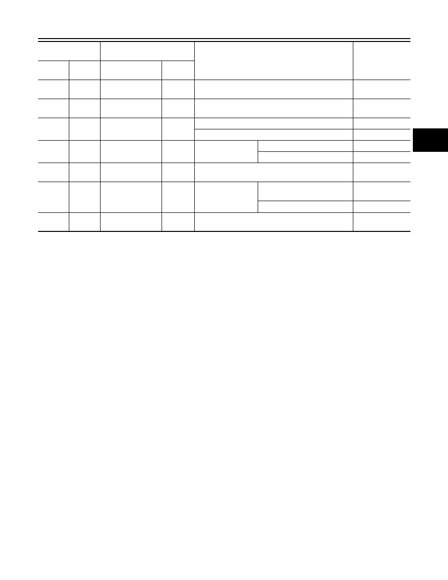
Terminal
(Wire color)
Description
Condition
Value (Approx.)
+
−
Signal name
Input/
Output
TM-322
< ECU DIAGNOSIS INFORMATION >
[7AT: RE7R01B (VK50VE)]
TCM
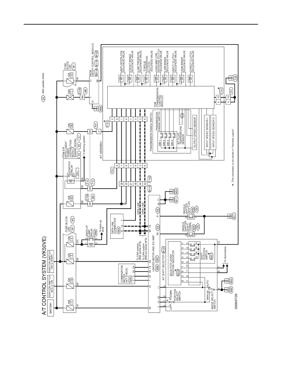
Wiring Diagram - A/T CONTROL SYSTEM -
INFOID:0000000005250332
JCDWA0558GB
Нет комментариевНе стесняйтесь поделиться с нами вашим ценным мнением.
Текст