Infiniti FX35, FX50 (S51). Manual — part 647

ON BOARD DIAGNOSTIC (OBD) SYSTEM
EC-129
< SYSTEM DESCRIPTION >
[VQ35HR]
C
D
E
F
G
H
I
J
K
L
M
A
EC
N
P
O
ENG OIL TEMP
°
C or
°
F
• The engine oil temperature (determined by the
signal voltage of the engine oil temperature sen-
sor) is displayed.
TRVL AFTER MIL
km or mile
• Distance traveled while MIL is activated.
A/F S1 HTR (B1)
%
• Air fuel ratio (A/F) sensor 1 heater control value
computed by ECM according to the input signals.
• The current flow to the heater becomes larger as
the value increases.
A/F S1 HTR (B2)
AC PRESS SEN
V
• The signal voltage from the refrigerant pressure
sensor is displayed.
VHCL SPEED SE
km/h or mph
• The vehicle speed computed from the vehicle
speed signal sent from unified meter and A/C
amp. is displayed.
SET VHCL SPD
km/h or mph
• The preset vehicle speed is displayed.
MAIN SW
ON/OFF
• Indicates [ON/OFF] condition from MAIN switch
signal.
CANCEL SW
ON/OFF
• Indicates [ON/OFF] condition from CANCEL
switch signal.
RESUME/ACC SW
ON/OFF
• Indicates [ON/OFF] condition from RESUME/AC-
CELERATE switch signal.
SET SW
ON/OFF
• Indicates [ON/OFF] condition from SET/COAST
switch signal.
BRAKE SW1
ON/OFF
• Indicates [ON/OFF] condition from ASCD brake
switch signal.
BRAKE SW2
ON/OFF
• Indicates [ON/OFF] condition of stop lamp switch
signal.
DIST SW
ON/OFF
• Indicates [ON/OFF] condition from DISTANCE
switch signal.
VHCL SPD CUT
NON/CUT
• Indicates the vehicle cruise condition.
NON: Vehicle speed is maintained at the ASCD
set speed.
CUT: Vehicle speed decreased to excessively
low compared with the ASCD set speed, and
ASCD operation is cut off.
LO SPEED CUT
NON/CUT
• Indicates the vehicle cruise condition.
NON: Vehicle speed is maintained at the ASCD
set speed.
CUT: Vehicle speed decreased to excessively
low, and ASCD operation is cut off.
AT OD MONITOR
ON/OFF
• Indicates [ON/OFF] condition of A/T O/D accord-
ing to the input signal from the TCM.
AT OD CANCEL
ON/OFF
• Indicates [ON/OFF] condition of A/T O/D cancel
request signal.
CRUISE LAMP
ON/OFF
• Indicates [ON/OFF] condition of CRUISE indica-
tor determined by the ECM according to the input
signals.
SET LAMP
ON/OFF
• Indicates [ON/OFF] condition of SET indicator
determined by the ECM according to the input
signals.
EXH V/T LEARN
YET/CMPLT
• Display the condition of Exhaust Valve Timing
Control Learning
YET: Exhaust Valve Timing Control Learning has
not been performed yet.
CMPLT: Exhaust Valve Timing Control Learning
has already been performed successfully.
Monitored item
Unit
Description
Remarks

EC-130
< SYSTEM DESCRIPTION >
[VQ35HR]
ON BOARD DIAGNOSTIC (OBD) SYSTEM
NOTE:
Any monitored item that does not match the vehicle being diagnosed is deleted from the display automatically.
ACTIVE TEST MODE
Test Item
BAT CUR SEN
mV
• The signal voltage of battery current sensor is
displayed.
ALT DUTY SIG
ON/OFF
• The control condition of the power generation
voltage variable control (determined by ECM ac-
cording to the input signals) is indicated.
ON: Power generation voltage variable control is
active.
OFF: Power generation voltage variable control
is inactive.
A/F ADJ-B1
—
• Indicates the correction of factor stored in ECM.
The factor is calculated from the difference be-
tween the target air-fuel ratio stored in ECM and
the air-fuel ratio calculated from A/F sensor 1 sig-
nal.
A/F ADJ-B2
FAN DUTY
%
• Indicates a command value for cooling fan. The
value is calculated by ECM based on input sig-
nals.
AC EVA TEMP
°
C or
°
F
• Indicates A/C evaporator temperature sent from
“unified meter and A/C amp.”.
AC EVA TARGET
°
C or
°
F
• Indicates target A/C evaporator temperature sent
from “unified meter and A/C amp.”.
ALT DUTY
%
• Indicates the duty ratio of the power generation
command value. The ratio is calculated by ECM
based on the battery current sensor signal.
Monitored item
Unit
Description
Remarks
TEST ITEM
CONDITION
JUDGMENT
CHECK ITEM (REMEDY)
FUEL INJEC-
TION
• Engine: Return to the original
non-standard condition
• Change the amount of fuel injec-
tion using CONSULT-III.
If malfunctioning symptom disap-
pears, see CHECK ITEM.
• Harness and connectors
• Fuel injector
• Air fuel ratio (A/F) sensor 1
IGNITION TIM-
ING
• Engine: Return to the original
non-standard condition
• Timing light: Set
• Retard the ignition timing using
CONSULT-III.
If malfunctioning symptom disap-
pears, see CHECK ITEM.
• Perform Idle Air Volume Learning.
POWER BAL-
ANCE
• Engine: After warming up, idle the
engine.
• A/C switch OFF
• Selector lever: P or N
• Cut off each injector signal one at
a time using CONSULT-III.
Engine runs rough or stops.
• Harness and connectors
• Compression
• Fuel injector
• Power transistor
• Spark plug
• Ignition coil
ENG COOLANT
TEMP
• Engine: Return to the original
non-standard condition
• Change the engine coolant tem-
perature using CONSULT-III.
If malfunctioning symptom disap-
pears, see CHECK ITEM.
• Harness and connectors
• Engine coolant temperature sen-
sor
• Fuel injector
FUEL PUMP RE-
LAY
• Ignition switch: ON (Engine
stopped)
• Turn the fuel pump relay ON and
OFF using CONSULT-III and lis-
ten to operating sound.
Fuel pump relay makes the operat-
ing sound.
• Harness and connectors
• Fuel pump relay

ON BOARD DIAGNOSTIC (OBD) SYSTEM
EC-131
< SYSTEM DESCRIPTION >
[VQ35HR]
C
D
E
F
G
H
I
J
K
L
M
A
EC
N
P
O
*: Leaving cooling fan OFF with CONSULT-III while engine is running may cause the engine to overheat.
DTC & SRT CONFIRMATION MODE
SRT STATUS Mode
For details, refer to
EC-111, "Diagnosis Description"
SRT WORK SUPPORT Mode
This mode enables a technician to drive a vehicle to set the SRT while monitoring the SRT status.
DTC WORK SUPPORT Mode
PURG VOL
CONT/V
• Engine: After warming up, run en-
gine at 1,500 rpm.
• Change the EVAP canister purge
volume control solenoid valve
opening percent using CON-
SULT-III.
Engine speed changes according to
the opening percent.
• Harness and connectors
• Solenoid valve
FUEL/T TEMP
SEN
• Change the fuel tank temperature using CONSULT-III.
VENT CON-
TROL/V
• Ignition switch: ON (Engine
stopped)
• Turn solenoid valve ON and OFF
with the CONSULT-III and listen
to operating sound.
Solenoid valve makes an operating
sound.
• Harness and connectors
• Solenoid valve
INT V/T ASSIGN
ANGLE
• Engine: Return to the original
non-standard condition
• Change intake valve timing using
CONSULT-III.
If malfunctioning symptom disap-
pears, see CHECK ITEM.
• Harness and connectors
• Intake valve timing control sole-
noid valve
EXH V/T ASSIGN
ANGLE
• Engine: Return to the original
non-standard condition
• Change exhaust valve timing us-
ing CONSULT-III.
If malfunctioning symptom disap-
pears, see CHECK ITEM.
• Harness and connectors
• Exhaust valve timing control mag-
net retarder
FAN DUTY CON-
TROL*
• Ignition switch: ON
• Change duty ratio using CON-
SULT-III.
Cooling fan speed changes.
• Harness and connectors
• Cooling fan motor
• Cooling fan relay
• Cooling fan control module
• IPDM E/R
ALTERNATOR
DUTY
• Engine: Idle
• Change duty ratio using CON-
SULT-III.
Battery voltage changes.
• Harness and connectors
• IPDM E/R
• Alternator
TEST ITEM
CONDITION
JUDGMENT
CHECK ITEM (REMEDY)
Test mode
Test item
Corresponding DTC No.
Reference page
EVAPORATIVE SYSTEM
EVP SML LEAK P0442/P1442*
P0442
P0455
EVP V/S LEAK P0456/P1456*
P0456
PURG VOL CN/V P1444
P0443
PURG FLOW P0441
P0441
A/F SEN1
A/F SEN1 (B1) P1278/P1279
P0133
A/F SEN1 (B1) P1276
P0130
A/F SEN1 (B2) P1288/P1289
P0153
A/F SEN1 (B2) P1286
P0150
EC-132
< SYSTEM DESCRIPTION >
[VQ35HR]
ON BOARD DIAGNOSTIC (OBD) SYSTEM
*: DTC P1442 and P1456 does not apply to S51 models but appears in DTC Work Support Mode screens.
Diagnosis Tool Function
INFOID:0000000005236733
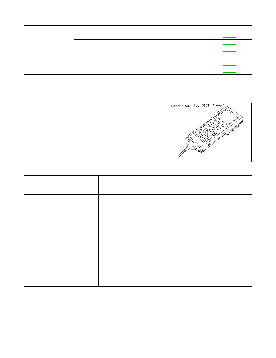
DESCRIPTION
Generic Scan Tool (OBD II scan tool) complying with SAE J1978/
ISO 15031-4 has 8 different functions explained below.
ISO15765-4 is used as the protocol.
The name “GST” or “Generic Scan Tool” is used in this service man-
ual.
FUNCTION
HO2S2
HO2S2 (B1) P1146
P0138
HO2S2 (B1) P1147
P0137
HO2S2 (B1) P0139
P0139
HO2S2 (B2) P1166
P0158
HO2S2 (B2) P1167
P0157
HO2S2 (B2) P0159
P0159
Test mode
Test item
Corresponding DTC No.
Reference page
SEF139P
Diagnostic Service
Function
Service $01
READINESS TESTS
This diagnostic service gains access to current emission-related data values, including an-
alog inputs and outputs, digital inputs and outputs, and system status information.
Service $02
(FREEZE DATA)
This diagnostic service gains access to emission-related data value that were stored by
ECM during the freeze frame. For details, refer to
Service $03
DTCs
This diagnostic service gains access to emission-related power train trouble codes which
were stored by ECM.
Service $04
CLEAR DIAG INFO
This diagnostic service can clear all emission-related diagnostic information. This in-
cludes:
• Clear number of diagnostic trouble codes (Service $01)
• Clear diagnostic trouble codes (Service $03)
• Clear trouble code for freeze frame data (Service $01)
• Clear freeze frame data (Service $02)
• Reset status of system monitoring test (Service $01)
• Clear on board monitoring test results (Service $06 and $07)
Service $06
(ON BOARD TESTS)
This diagnostic service accesses the results of on board diagnostic monitoring tests of
specific components/systems that are not continuously monitored.
Service $07
(ON BOARD TESTS)
This diagnostic service enables the off board test drive to obtain test results for emission-
related powertrain components/systems that are continuously monitored during normal
driving conditions.
Нет комментариевНе стесняйтесь поделиться с нами вашим ценным мнением.
Текст