Infiniti FX35, FX50 (S51). Manual — part 1826

P1815 M-MODE SWITCH
TM-111
< DTC/CIRCUIT DIAGNOSIS >
[7AT: RE7R01A (VQ35HR)]
C
E
F
G
H
I
J
K
L
M
A
B
TM
N
O
P
P1815 M-MODE SWITCH
Description
INFOID:0000000005250100
• The manual mode switch [manual mode select switch and manual mode position select switch (shift-up/shift-
down)] is installed in the A/T shift selector assembly. It transmits manual mode switch, shift up and shift
down switch signals to unified meter and A/C amp. Then unified meter and A/C amp. transmits signals to
TCM via CAN communication.
• Manual mode select switch transmits manual mode switch signal or non-manual mode switch signal to uni-
fied meter and A/C amp. Then TCM receives signals from unified meter and A/C amp. via CAN communica-
tion.
• The manual mode position select switch (shift-up) transmits manual mode shift up signal to the unified meter
and A/C amp. Then TCM receives signal from the unified meter and A/C amp. via CAN communication.
• The manual mode position select switch (shift-down) transmits manual mode shift down signal to the unified
meter and A/C amp. Then TCM receives signal from the unified meter and A/C amp. via CAN communica-
tion.
• The TCM transmits manual mode indicator signal to the unified meter and A/C amp. via CAN communication
line.
DTC Logic
INFOID:0000000005250101
DTC DETECTION LOGIC
DTC CONFIRMATION PROCEDURE
1.
PRECONDITIONING
If “DTC CONFIRMATION PROCEDURE” has been previously conducted, always turn ignition switch OFF and
wait at least 10 seconds before conducting the next test.
>> GO TO 2.
2.
CHECK DTC DETECTION
With CONSULT-III
1.
Turn ignition switch ON.
2.
Select “SLCT LVR POSI” and “MANU MODE SW” in “Data Monitor” in “TRANSMISSION”.
3.
Maintain the following each conditions more than 2 seconds.
4.
Perform “Self Diagnostic Results” in “TRANSMISSION”.
Is “P1815” detected?
YES
>> Go to
.
NO
>> INSPECTION END
Diagnosis Procedure
INFOID:0000000005250102
1.
CHECK MANUAL MODE SWITCH CIRCUIT
1.
Turn ignition switch OFF.
2.
Disconnect A/T shift selector connector.
3.
Turn ignition switch ON.
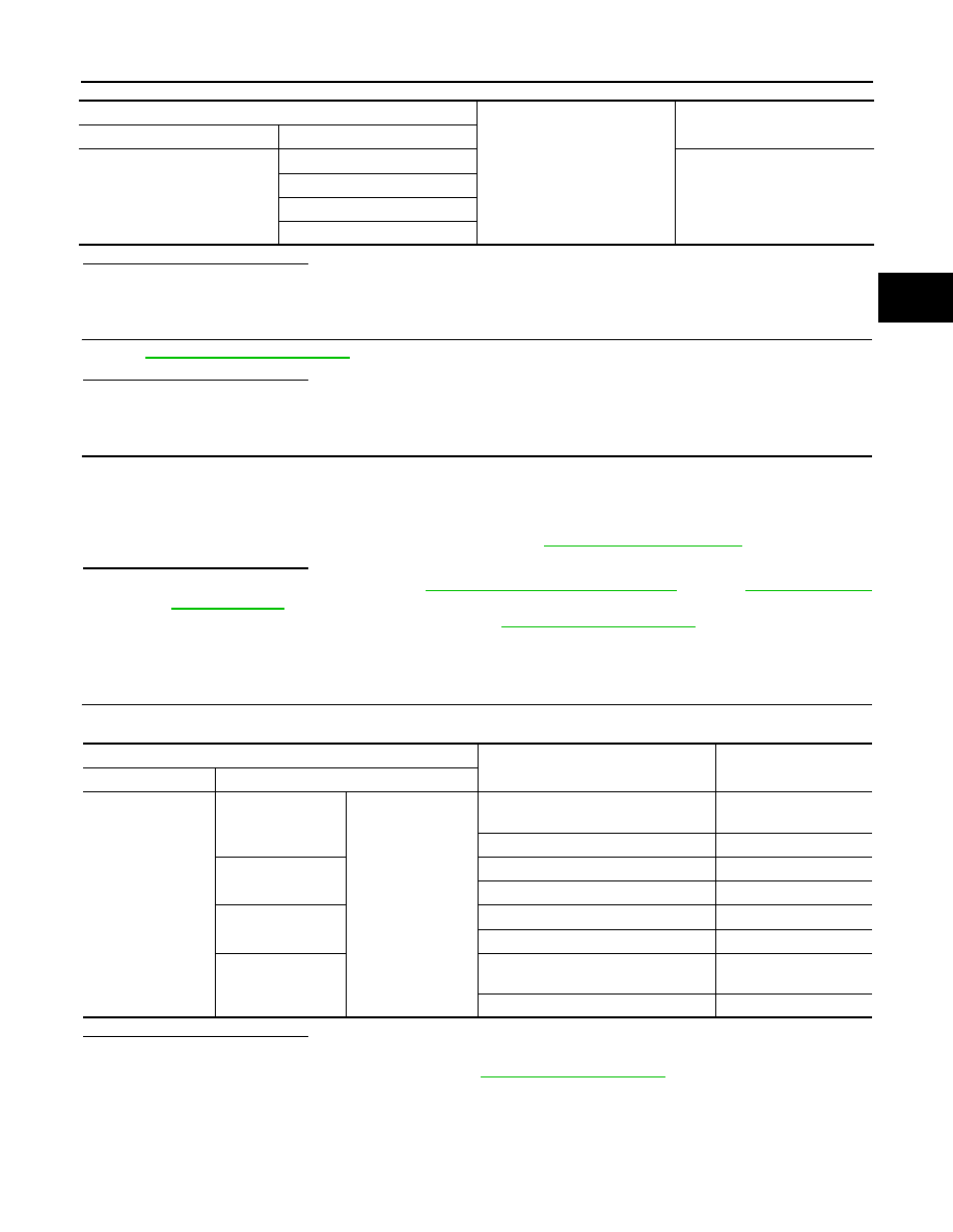
DTC
Trouble diagnosis name
DTC is detected if...
Possible cause
P1815
Manual Mode Switch Circuit
TCM monitors manual mode,
non manual mode, up or down
switch signal, and detects as ir-
regular when impossible input
pattern occurs 2 second or
more.
• Harness or connectors
(These switches circuit is
open or shorted.)
• Manual mode select switch
(Into A/T shift selector)
• Manual mode position select
switch (Into A/T shift selector)
SLCT LVR POSI
: D
MANU MODE SW
: ON

TM-112
< DTC/CIRCUIT DIAGNOSIS >
[7AT: RE7R01A (VQ35HR)]
P1815 M-MODE SWITCH
4.
Check voltage between A/T shift selector vehicle side harness connector terminals.
Is the inspection result normal?
YES
>> GO TO 2.
NO
>> GO TO 3.
2.
CHECK MANUAL MODE SWITCH
1.
Turn ignition switch OFF.
2.
Check manual mode switch. Refer to
TM-113, "Component Inspection (Manual Mode Switch)"
.
Is the inspection result normal?
YES
>> GO TO 6.
NO
>> Repair or replace damaged parts.
3.
CHECK GROUND CIRCUIT
1.
Turn ignition switch OFF.
2.
Check continuity between A/T shift selector vehicle side harness connector terminal and ground.
Is the inspection result normal?
YES
>> GO TO 4.
NO
>> Repair or replace damaged parts.
4.
CHECK HARNESS BETWEEN A/T SHIFT SELECTOR AND UNIFIED METER AND A/C AMP. (STEP 1)
1.
Disconnect unified meter and A/C amp. connector.
2.
Check continuity between A/T shift selector vehicle side harness connector terminals and unified meter
and A/C amp. vehicle side harness connector terminals.
Is the inspection result normal?
YES
>> GO TO 5.
NO
>> Repair or replace damaged parts.
5.
CHECK HARNESS BETWEEN A/T SHIFT SELECTOR AND UNIFIED METER AND A/C AMP. (STEP 2)
Check continuity between A/T shift selector vehicle side harness connector terminals and ground.
A/T shift selector vehicle side harness connector
Voltage (Approx.)
Connector
Terminal
+
−
M137
1
4
Battery voltage
2
3
5
A/T shift selector vehicle side harness connector
Ground
Continuity
Connector
Terminal
M137
4
Existed
A/T shift selector vehicle side harness connector
Unified meter and A/C amp. vehicle side harness
connector
Continuity
Connector
Terminal
Connector
Terminal
M137
1
M66
10
Existed
2
25
3
5
5
11
P1815 M-MODE SWITCH
TM-113
< DTC/CIRCUIT DIAGNOSIS >
[7AT: RE7R01A (VQ35HR)]
C
E
F
G
H
I
J
K
L
M
A
B
TM
N
O
P
Is the inspection result normal?
YES
>> GO TO 6.
NO
>> Repair or replace damaged parts.
6.
CHECK INTERMITTENT INCIDENT
GI-36, "Intermittent Incident"
.
Is the inspection result normal?
YES
>> GO TO 7.
NO
>> Repair or replace damaged parts.
7.
CHECK UNIFIED METER AND A/C AMP.
1.
Reconnect all the connectors.
2.
Turn ignition switch ON.
3.
Select “M RANGE SW”, “NM RANGE SW”, “AT SFT UP SW” and “AT SFT DWN SW” in “Data Monitor” in
“METER/M&A”.
4.
Check the On/Off operations of each monitor item. Refer to
Is the inspection result normal?
YES
>> Replace A/T assembly. Refer to
(AWD).
NO
>> Replace unified meter and A/C amp. Refer to
Component Inspection (Manual Mode Switch)
INFOID:0000000005250103
1.
CHECK MANUAL MODE SWITCH
Check continuity between A/T shift selector connector terminals.
Is the inspection result normal?
YES
>> INSPECTION END
NO
>> Repair or replace damaged parts. Refer to
A/T shift selector vehicle side harness connector
Ground
Continuity
Connector
Terminal
M137
1
Not existed
2
3
5
A/T shift selector connector
Condition
Continuity
Connector Terminal
M137
1
4
Selector lever is shifted to manual shift
gate side
Existed
Other than the above
Not existed
2
Selector lever is shifted to – side
Existed
Other than the above
Not existed
3
Selector lever is shifted to + side
Existed
Other than the above
Not existed
5
Selector lever is shifted to manual shift
gate side
Not existed
Other than the above
Existed

TM-114
< DTC/CIRCUIT DIAGNOSIS >
[7AT: RE7R01A (VQ35HR)]
P2713 PRESSURE CONTROL SOLENOID D
P2713 PRESSURE CONTROL SOLENOID D
Description
INFOID:0000000005250106
• The high and low reverse clutch solenoid valve is controlled by the TCM in response to signals transmitted
from the transmission range switch, output speed sensor and accelerator pedal position sensor. Gears will
then be shifted to the optimum position.
• The high and low reverse clutch solenoid valve controls the high and low reverse clutch control valve in
response to a signal transmitted from the TCM.
DTC Logic
INFOID:0000000005250107
DTC DETECTION LOGIC
DTC CONFIRMATION PROCEDURE
CAUTION:
Always drive vehicle at a safe speed.
1.
PRECONDITIONING
If “DTC CONFIRMATION PROCEDURE” has been previously conducted, always turn ignition switch OFF and
wait at least 10 seconds before conducting the next test.
>> GO TO 2.
2.
CHECK DTC DETECTION
With CONSULT-III
1.
Start the engine.
2.
Select “BATTERY VOLT”, “MANU MODE SW”, “GEAR” and “VHCL/S SE-A/T” in “Data Monitor” in
“TRANSMISSION”.
3.
Drive the vehicle and maintain the following conditions for 5 seconds or more.
4.
Perform “Self Diagnostic Results” in “TRANSMISSION”.
With GST
Follow the procedure “With CONSULT-III”.
Is “P2713” detected?
YES
>> Go to
NO
>> INSPECTION END
Diagnosis Procedure
INFOID:0000000005250108
1.
CHECK INTERMITTENT INCIDENT
GI-36, "Intermittent Incident"
Is the inspection result normal?
YES
>> Replace A/T assembly. Refer to
(2WD),
(AWD).
NO
>> Repair or replace damaged parts.
DTC
Trouble diagnosis name
DTC is detected if...
Possible cause
P2713
Pressure Control Solenoid D
A DTC is set if the high and low
reverse clutch solenoid valve
monitor value is 0.4 A or less
when the high and low reverse
clutch solenoid valve command
value is more than 0.75 A.
• Harness or connectors
(Solenoid valve circuit is
open or shorted.)
• High and low reverse clutch
solenoid valve
BATTERY VOLT
: 9 V or more
MANU MODE SW
: ON
GEAR
: 3rd
VHCL/S SE-A/T
: 10 km/h (7 MPH) or more
Нет комментариевНе стесняйтесь поделиться с нами вашим ценным мнением.
Текст