Infiniti FX35, FX50 (S51). Manual — part 913
VVEL CONTROL MODULE
EC-1193
< ECU DIAGNOSIS INFORMATION >
[VK50VE]
C
D
E
F
G
H
I
J
K
L
M
A
EC
N
P
O
VVEL CONTROL MODULE
Reference Value
INFOID:0000000005237655
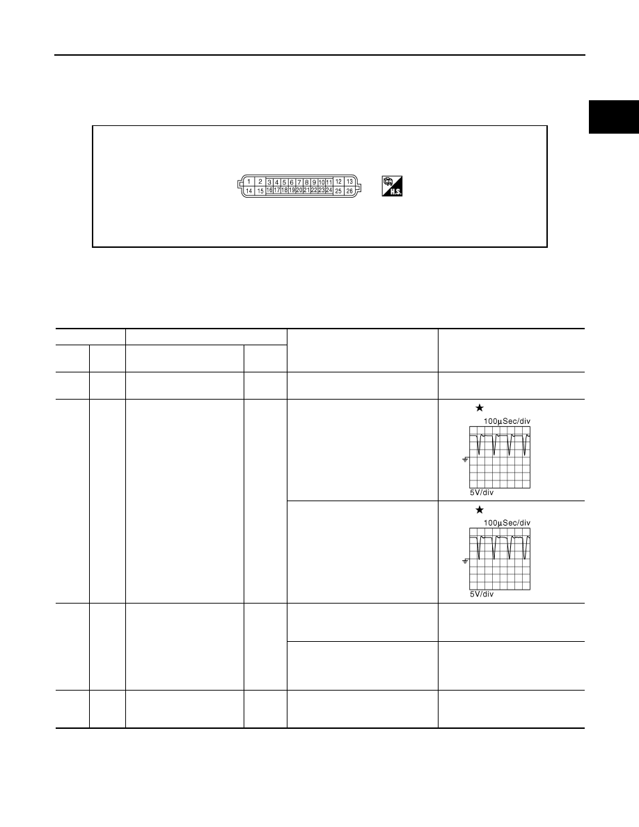
TERMINAL LAYOUT
PHYSICAL VALUES
NOTE:
• VVEL control module is located behind the IPDM E/R. For this inspection, remove hoodledge cover (RH).
• Specification data are reference values and are measured between each terminals.
• Pulse signal is measured by CONSULT-III.
JMBIA0857ZZ
Terminal No.
Description
Condition
Value
(Approx.)
+
–
Signal name
Input/
Output
1
(W)
14
(B)
VVEL actuator motor power
supply (bank 2)
Input
[Ignition switch: ON]
BATTERY VOLTAGE
(11 - 14V)
2
(BR)
14
(B)
VVEL actuator motor
(High lift) (bank 2)
Output
[Engine is running]
• Warm-up condition
• Idle speed
0 - 14 V
[Engine is running]
• Warm-up condition
• When revving engine up to 2,000
rpm quickly
0 - 14 V
3
(R)
6
(B)
VVEL control shaft position
sensor 1 (bank 1)
Input
[Engine is running]
• Warm-up condition
• Idle speed
0.25 - 1.40 V
[Engine is running]
• Warm-up condition
• When revving engine up to 3,000
rpm quickly
0.25 - 4.75 V
4
(B)
—
Sensor ground
[VVEL control shaft position
sensor 1 (bank 2)]
—
—
—
JMBIA0854ZZ
JMBIA0855ZZ
EC-1194
< ECU DIAGNOSIS INFORMATION >
[VK50VE]
VVEL CONTROL MODULE
5
(R)
4
(B)
VVEL control shaft position
sensor 1 (bank 2)
Input
[Engine is running]
• Warm-up condition
• Idle speed
0.25 - 1.40 V
[Engine is running]
• Warm-up condition
• When revving engine up to 3,000
rpm quickly
0.25 - 4.75 V
6
(B)
—
Sensor ground
[VVEL control shaft position
sensor 1 (bank 1)]
—
—
—
7
(W)
6
(B)
Sensor power supply
[VVEL control shaft position
sensor 1 (bank 1)]
—
[Ignition switch: ON]
5 V
8
(R)
14
(B)
Power supply for VVEL con-
trol module
—
[Ignition switch: ON]
BATTERY VOLTAGE
(11 - 14 V)
9
(W)
4
(B)
Sensor power supply
[VVEL position sensor 1
(bank 2)]
—
[Ignition switch: ON]
5 V
11
(G)
—
CAN communication line
[ECM]
Input/
Output
—
—
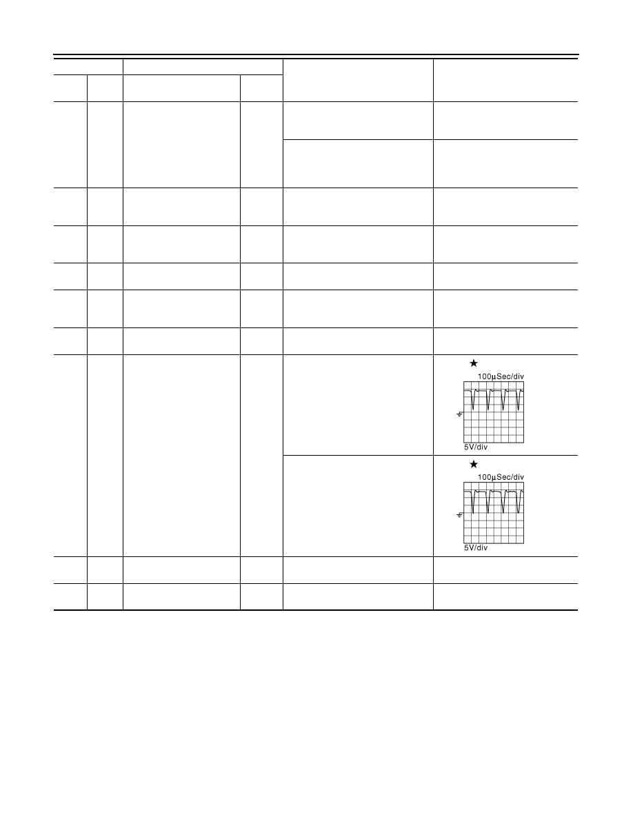
12
(G)
14
(B)
VVEL actuator motor
(High lift) (bank 1)
Output
[Engine is running]
• Warm-up condition
• Idle speed
0 - 14 V
[Engine is running]
• Warm-up condition
• When revving engine up to 3,000
rpm quickly
0 - 14 V
13
(W)
14
(B)
VVEL actuator motor power
supply (bank 1)
Input
[Ignition switch: ON]
BATTERY VOLTAGE
(11 - 14 V)
14
(B)
—
VVEL control module
ground
—
—
—
Terminal No.
Description
Condition
Value
(Approx.)
+
–
Signal name
Input/
Output
JMBIA0854ZZ
JMBIA0855ZZ
VVEL CONTROL MODULE
EC-1195
< ECU DIAGNOSIS INFORMATION >
[VK50VE]
C
D
E
F
G
H
I
J
K
L
M
A
EC
N
P
O
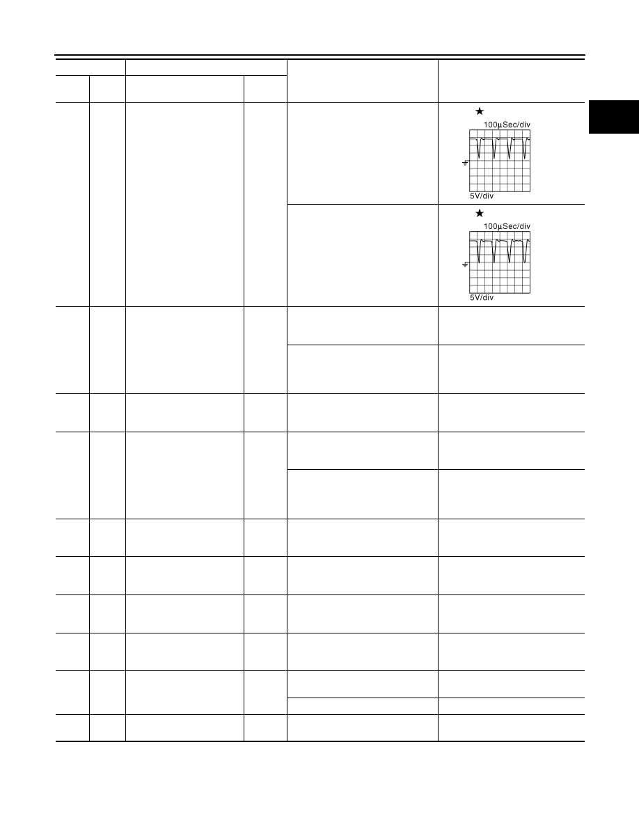
15
(G)
14
(B)
VVEL actuator motor
(Low lift) (bank 2)
Output
[Engine is running]
• Warm-up condition
• Idle speed
0 - 14 V
[Engine is running]
• Warm-up condition
• When revving engine up to 3,000
rpm quickly
0 - 14 V
16
(G)
19
(L)
VVEL control shaft position
sensor 2 (bank 1)
Input
[Engine is running]
• Warm-up condition
• Idle speed
3.50 - 4.75 V
[Engine is running]
• Warm-up condition
• When revving engine up to 3,000
rpm quickly
0.25 - 4.75 V
17
(L)
—
Sensor ground
[VVEL control shaft position
sensor 2 (bank 2)]
—
—
—
18
(G)
17
(L)
VVEL control shaft position
sensor 2 (bank 2)
Input
[Engine is running]
• Warm-up condition
• Idle speed
3.50 - 4.75 V
[Engine is running]
• Warm-up condition
• When revving engine up to 3,000
rpm quickly
0.25 - 4.75 V
19
(L)
—
Sensor ground
[VVEL control shaft position
sensor 2 (bank 1)]
—
—
—
20
(Y)
19
(L)
Sensor power supply
[VVEL control shaft position
sensor 2 (bank 1)]
—
[Ignition switch: ON]
5 V
21
(V)
14
(B)
VVEL actuator motor relay
abort signal
[ECM]
Input
[Engine is running]
• Warm-up condition
• Idle speed
0 V
22
(Y)
17
(L)
Sensor power supply
[VVEL control shaft position
sensor 2 (bank 2)]
—
[Ignition switch: ON]
5 V
23
(L)
14
(B)
VVEL control motor relay
Output
[Ignition switch: OFF]
BATTERY VOLTAGE
(11 - 14 V)
[Ignition switch: ON]
0 - 1.0 V
24
(R)
—
CAN communication line
[ECM]
Input/
Output
—
—
Terminal No.
Description
Condition
Value
(Approx.)
+
–
Signal name
Input/
Output
JMBIA0854ZZ
JMBIA0855ZZ

EC-1196
< ECU DIAGNOSIS INFORMATION >
[VK50VE]
VVEL CONTROL MODULE
: Average voltage for pulse signal (Actual pulse signal can be confirmed by oscilloscope.)
25
(BR)
14
(B)
VVEL control motor
(Low lift) (bank 1)
Output
[Engine is running]
• Warm-up condition
• Idle speed
0 - 14 V
[Engine is running]
• Warm-up condition
• When revving engine up to 3,000
rpm quickly
0 - 14 V
Terminal No.
Description
Condition
Value
(Approx.)
+
–
Signal name
Input/
Output
JMBIA0854ZZ
JMBIA0855ZZ
Нет комментариевНе стесняйтесь поделиться с нами вашим ценным мнением.
Текст