Infiniti FX35, FX50 (S51). Manual — part 843
P0448 EVAP CANISTER VENT CONTROL VALVE
EC-913
< DTC/CIRCUIT DIAGNOSIS >
[VK50VE]
C
D
E
F
G
H
I
J
K
L
M
A
EC
N
P
O
• EVAP hose between EVAP canister and vehicle frame for clogging or poor connection
>> Repair hose or replace EVAP canister.
6.
CHECK EVAP CONTROL SYSTEM PRESSURE SENSOR CONNECTOR
1.
Disconnect EVAP control system pressure sensor harness connector.
2.
Check that water is not inside connectors.
Is the inspection result normal?
YES
>> GO TO 7.
NO
>> Replace EVAP control system pressure sensor.
7.
CHECK EVAP CONTROL SYSTEM PRESSURE SENSOR
EC-917, "Component Inspection"
Is the inspection result normal?
YES
>> GO TO 8.
NO
>> Replace EVAP control system pressure sensor.
8.
CHECK INTERMITTENT INCIDENT
GI-36, "Intermittent Incident"
.
>> INSPECTION END
Component Inspection
INFOID:0000000005237383
1.
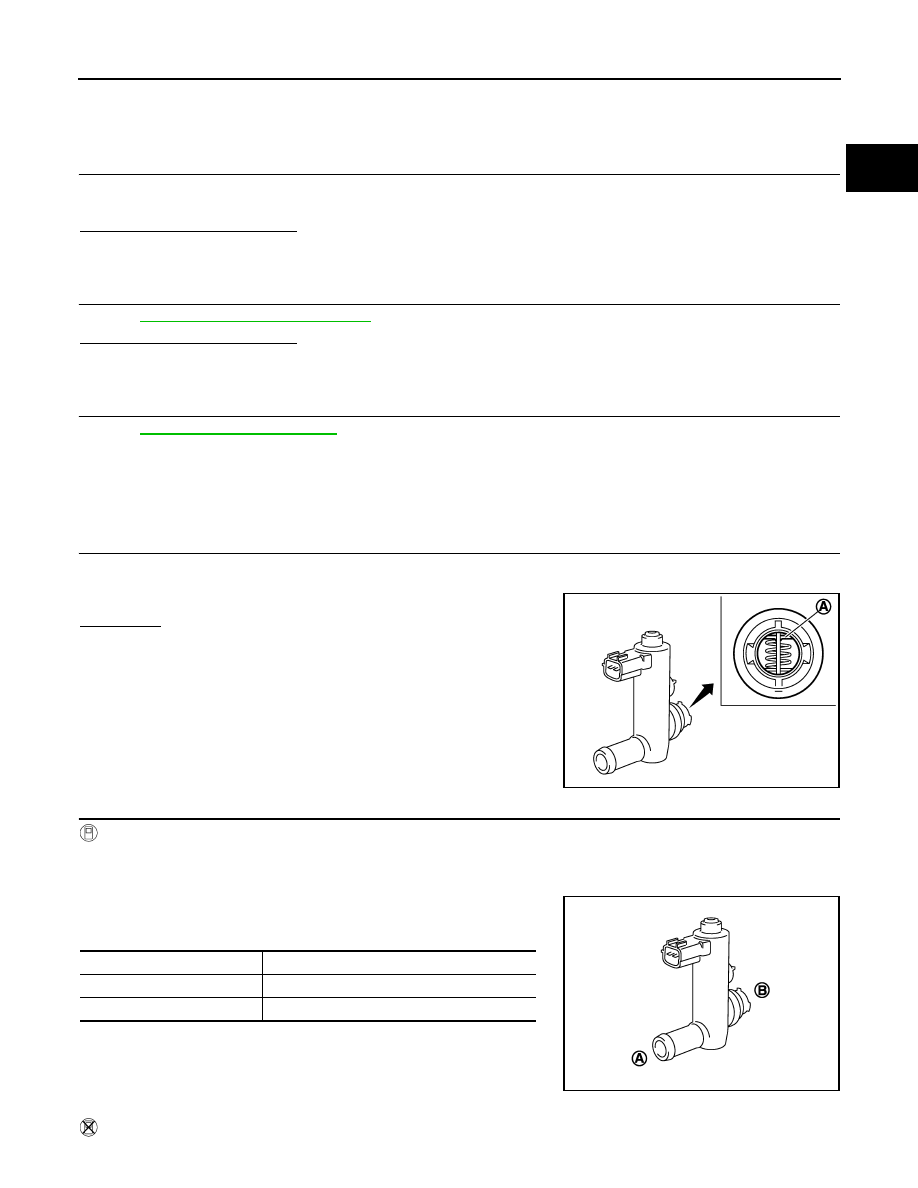
CHECK EVAP CANISTER VENT CONTROL VALVE-I
1.
Turn ignition switch OFF.
2.
Remove EVAP canister vent control valve from EVAP canister.
3.
Check portion (A) of EVAP canister vent control valve for rust.
Is it rusted?
YES
>> Replace EVAP canister vent control valve
NO
>> GO TO 2.
2.
CHECK EVAP CANISTER VENT CONTROL VALVE-II
With CONSULT-III
1.
Reconnect harness connectors disconnected.
2.
Turn ignition switch ON.
3.
Perform “VENT CONTROL/V” in “ACTIVE TEST” mode.
4.
Check air passage continuity and operation delay time.
Check that new O-ring is installed properly.
Operation takes less than 1 second.
Without CONSULT-III
JMBIA0168ZZ
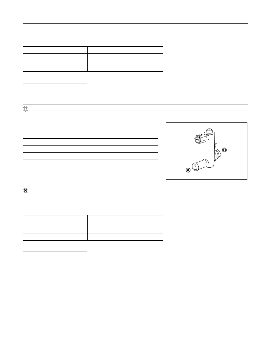
VENT CONTROL/V Condition
Air passage continuity between (A) and (B)
ON
Not existed
OFF
Existed
JMBIA0169ZZ
EC-914
< DTC/CIRCUIT DIAGNOSIS >
[VK50VE]
P0448 EVAP CANISTER VENT CONTROL VALVE
1.
Disconnect EVAP canister vent control valve harness connector.
2.
Check air passage continuity and operation delay time under the following conditions.
Check that new O-ring is installed properly.
Operation takes less than 1 second.
Is the inspection result normal?
YES
>> GO TO 3.
NO
>> Replace EVAP canister vent control valve
3.
CHECK EVAP CANISTER VENT CONTROL VALVE-III
With CONSULT-III
1.
Clean the air passage [portion (A) to (B)] of EVAP canister vent control valve using an air blower.
2.
Perform “VENT CONTROL/V” in “ACTIVE TEST” mode.
3.
Check air passage continuity and operation delay time.
Check that new O-ring is installed properly.
Operation takes less than 1 second.
Without CONSULT-III
1.
Clean the air passage [portion (A) to (B)] of EVAP canister vent control valve using an air blower.
2.
Check air passage continuity and operation delay time under the following conditions.
Check that new O-ring is installed properly.
Operation takes less than 1 second.
Is the inspection result normal?
YES
>> INSPECTION END
NO
>> Replace EVAP canister vent control valve
Condition
Air passage continuity between (A) and (B)
12 V direct current supply between
terminals 1 and 2
Not existed
OFF
Existed
VENT CONTROL/V Condition
Air passage continuity between (A) and (B)
ON
Not existed
OFF
Existed
JMBIA0169ZZ
Condition
Air passage continuity between (A) and (B)
12 V direct current supply between
terminals 1 and 2
Not existed
OFF
Existed
P0451 EVAP CONTROL SYSTEM PRESSURE SENSOR
EC-915
< DTC/CIRCUIT DIAGNOSIS >
[VK50VE]
C
D
E
F
G
H
I
J
K
L
M
A
EC
N
P
O
P0451 EVAP CONTROL SYSTEM PRESSURE SENSOR
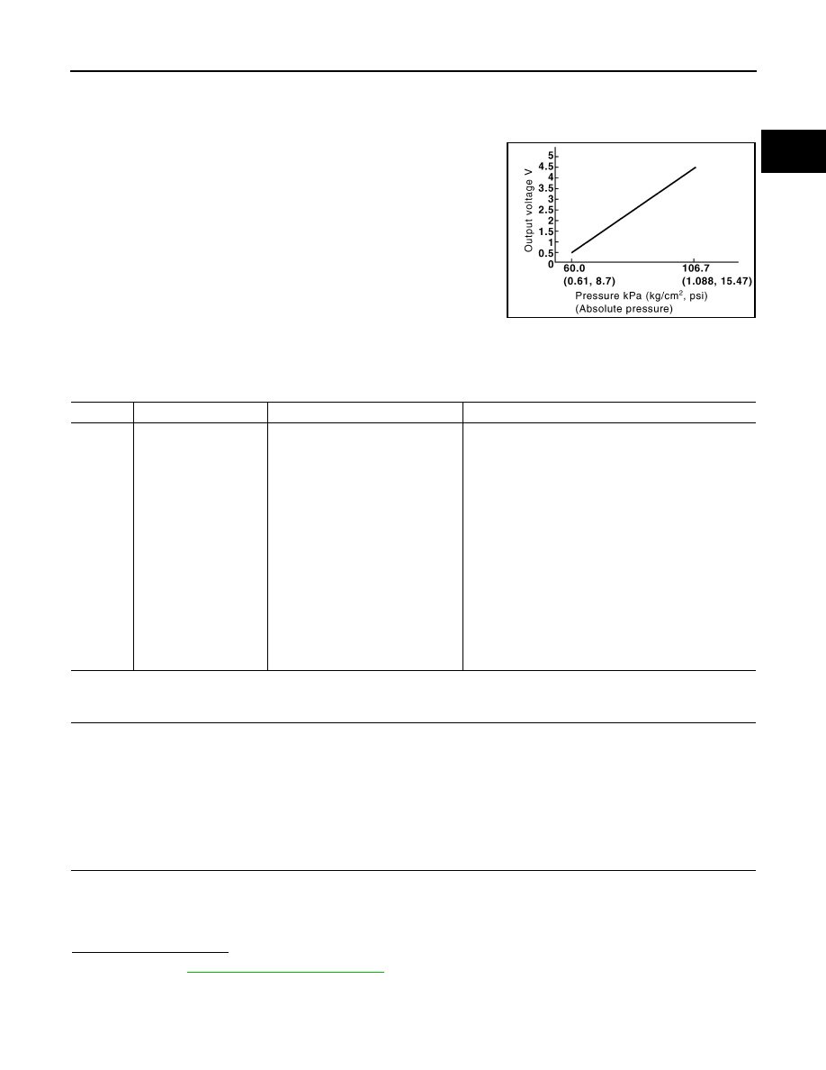
Description
INFOID:0000000005237384
The EVAP control system pressure sensor detects pressure in the
purge line. The sensor output voltage to the ECM increases as pres-
sure increases.
DTC Logic
INFOID:0000000005237385
DTC DETECTION LOGIC
DTC CONFIRMATION PROCEDURE
1.
PRECONDITIONING
If DTC Confirmation Procedure has been previously conducted, always perform the following procedure
before conducting the next test.
1.
Turn ignition switch OFF and wait at least 10 seconds.
2.
Turn ignition switch ON.
3.
Turn ignition switch OFF and wait at least 10 seconds.
>> GO TO 2.
2.
PERFORM DTC CONFIRMATION PROCEDURE
1.
Start engine and wait at least 40 seconds.
NOTE:
Do not depress accelerator pedal even slightly.
2.
Check 1st trip DTC.
Is 1st trip DTC detected?
YES
>> Go to
NO
>> INSPECTION END
PBIB3370E
DTC No.
Trouble diagnosis name
DTC detecting condition
Possible cause
P0451
EVAP control system
pressure sensor perfor-
mance
ECM detects a sloshing signal from
the EVAP control system pressure
sensor
• Harness or connectors
(EVAP control system pressure sensor circuit is short-
ed.)
(APP sensor 2 circuit is shorted.)
(Battery current sensor circuit is shorted.)
[Camshaft position sensor (bank 1) circuit is shorted.]
(Crankshaft position sensor circuit is shorted.)
[Exhaust valve timing control position sensor (bank 1)
circuit is shorted.]
(Manifold absolute pressure sensor circuit is shorted.)
• EVAP control system pressure sensor
• Accelerator pedal position sensor
• Battery current sensor
• Camshaft position sensor (bank 1)
• Crankshaft position sensor
• Exhaust valve timing control position sensor (bank 1)
• Manifold absolute pressure sensor

EC-916
< DTC/CIRCUIT DIAGNOSIS >
[VK50VE]
P0451 EVAP CONTROL SYSTEM PRESSURE SENSOR
Diagnosis Procedure
INFOID:0000000005237386
1.
CHECK GROUND CONNECTION
1.
Turn ignition switch OFF.
2.
Check ground connection M95. Refer to Ground Inspection in
Is the inspection result normal?
YES
>> GO TO 2.
NO
>> Repair or replace ground connection.
2.
CHECK EVAP CONTROL SYSTEM PRESSURE SENSOR CONNECTOR
1.
Disconnect EVAP control system pressure sensor harness connector.
2.
Check that water is not inside connectors.
Is the inspection result normal?
YES
>> GO TO 3.
NO
>> Repair or replace harness connector.
3.
CHECK EVAP CONTROL SYSTEM PRESSURE SENSOR POWER SUPPLY CIRCUIT
1.
Turn ignition switch ON.
2.
Check the voltage between EVAP control system pressure sensor harness connector and ground.
Is the inspection result normal?
YES
>> GO TO 8.
NO
>> GO TO 4.
4.
CHECK SENSOR POWER SUPPLY CIRCUIT
Check harness for short to power and short to ground, between the following terminals.
Is the inspection result normal?
YES
>> GO TO 5.
NO
>> Repair short to ground or short to power in harness or connectors.
5.
CHECK COMPONENTS
Check the following.
• Battery current sensor (Refer to
EC-1025, "Component Inspection"
.)
• Camshaft position sensor (bank 1) (Refer to
EC-881, "Component Inspection"
• Crankshaft position sensor (Refer to
EC-876, "Component Inspection"
• Exhaust valve timing control position sensor (bank 1) (Refer to
EC-978, "Component Inspection"
.)
• Manifold absolute pressure sensor (Refer to
EC-785, "Component Inspection"
Is the inspection result normal?
EVAP control system
pressure sensor
Ground
Voltage (V)
Connector
Terminal
B252
3
Ground
Approx. 5
ECM
Sensor
Connector
Terminal
Name
Connector
Terminal
F111
87
Crankshaft position sensor
F2
1
91
Camshaft position sensor (bank 1)
F84
1
EVT control position sensor (bank 1)
F59
1
95
Battery current sensor
E21
1
EVAP control system pressure sensor
B252
3
Manifold absolute pressure sensor
F65
3
M160
99
APP sensor 2 (Without ICC)
E112
6
APP sensor 2 (With ICC)
E116
3
Нет комментариевНе стесняйтесь поделиться с нами вашим ценным мнением.
Текст