Infiniti FX35, FX50 (S51). Manual — part 220
BCS
BCM (BODY CONTROL MODULE)
BCS-61
< ECU DIAGNOSIS INFORMATION >
C
D
E
F
G
H
I
J
K
L
B
A
O
P
N
92
(LG)
Ground
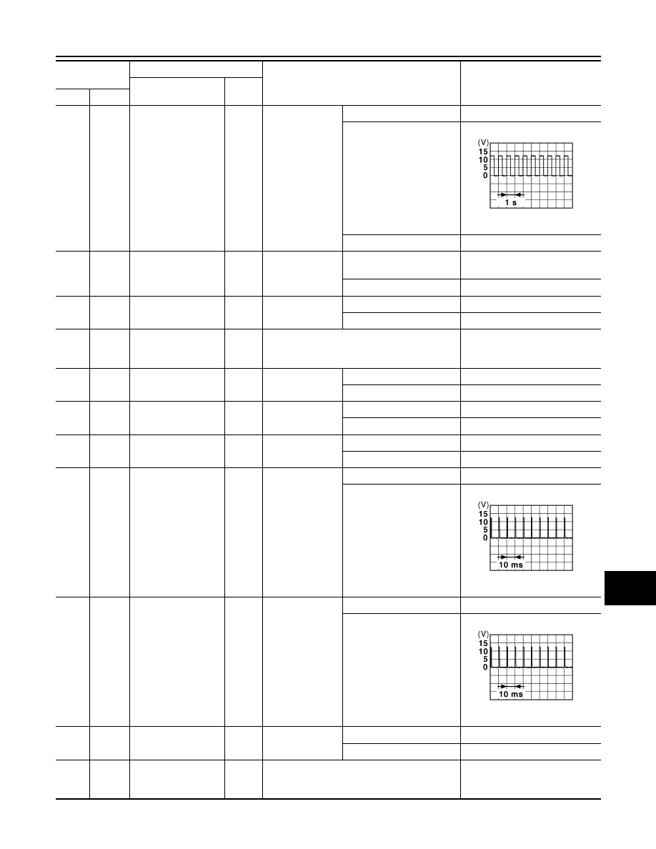
Key slot illumination
Output
Key slot illumina-
tion
OFF
12 V
Blinking
6.5 V
ON
0 V
93
(V)
Ground
ON indicator lamp
Output
Ignition switch
OFF (LOCK indicator is not
illuminated)
Battery voltage
ON or ACC
0 V
95
(O)
Ground
ACC relay control
Output
Ignition switch
OFF
0 V
ACC or ON
12 V
96
(GR)
Ground
A/T shift selector (De-
tention switch) power
supply
Output
—
12 V
97
(L)
Ground
Steering lock condi-
tion No. 1
Input
Steering lock
LOCK status
0 V
UNLOCK status
12 V
98
(P)
Ground
Steering lock condi-
tion No. 2
Input
Steering lock
LOCK status
12 V
UNLOCK status
0 V
99
(R)
Ground
Selector lever P posi-
tion switch
Input
Selector lever
P position
0 V
Any position other than P
12 V
100
(G)
Ground
Passenger door re-
quest switch
Input
Passenger door
request switch
ON (Pressed)
0 V
OFF (Not pressed)
1.0 V
101
(SB)
Ground
Driver door request
switch
Input
Driver door re-
quest switch
ON (Pressed)
0 V
OFF (Not pressed)
1.0 V
102
(O)
Ground
Blower fan motor re-
lay control
Output
Ignition switch
OFF or ACC
0 V
ON
12 V
103
(BR)
Ground
Remote keyless entry
receiver power sup-
ply
Output
Ignition switch OFF
12 V
Terminal No.
(Wire color)
Description
Condition
Value
(Approx.)
Signal name
Input/
Output
+
–
JPMIA0015GB
JPMIA0016GB
JPMIA0016GB
BCS-62
< ECU DIAGNOSIS INFORMATION >
BCM (BODY CONTROL MODULE)
106
(W)
Ground
Steering lock unit
power supply
Output
Ignition switch
OFF or ACC
12 V
ON
0 V
107
(LG)
Ground
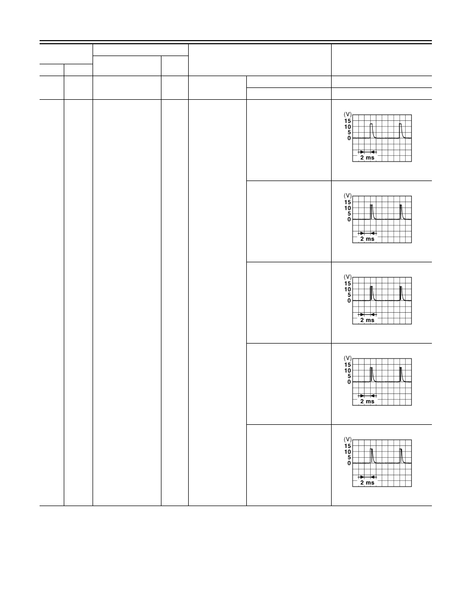
Combination switch
INPUT 1
Input
Combination
switch
(Wiper intermit-
tent dial 4)
All switches OFF
1.4 V
Turn signal switch LH
1.3 V
Turn signal switch RH
1.3 V
Front wiper switch LO
1.3 V
Front washer switch ON
1.3 V
Terminal No.
(Wire color)
Description
Condition
Value
(Approx.)
Signal name
Input/
Output
+
–
JPMIA0041GB
JPMIA0037GB
JPMIA0036GB
JPMIA0038GB
JPMIA0039GB
BCS
BCM (BODY CONTROL MODULE)
BCS-63
< ECU DIAGNOSIS INFORMATION >
C
D
E
F
G
H
I
J
K
L
B
A
O
P
N
108
(R)
Ground
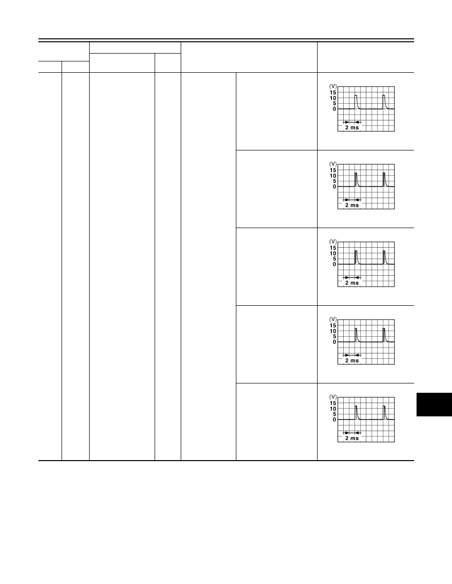
Combination switch
INPUT 4
Input
Combination
switch
All switches OFF
(Wiper intermittent dial 4)
1.4 V
Lighting switch AUTO
(Wiper intermittent dial 4)
1.3 V
Lighting switch 1ST
(Wiper intermittent dial 4)
1.3 V
Rear wiper switch INT
(Wiper intermittent dial 4)
1.3 V
Any of the conditions below
with all switches OFF
• Wiper intermittent dial 1
• Wiper intermittent dial 5
• Wiper intermittent dial 6
1.3 V
Terminal No.
(Wire color)
Description
Condition
Value
(Approx.)
Signal name
Input/
Output
+
–
JPMIA0041GB
JPMIA0038GB
JPMIA0036GB
JPMIA0040GB
JPMIA0039GB
BCS-64
< ECU DIAGNOSIS INFORMATION >
BCM (BODY CONTROL MODULE)
109
(Y)
Ground
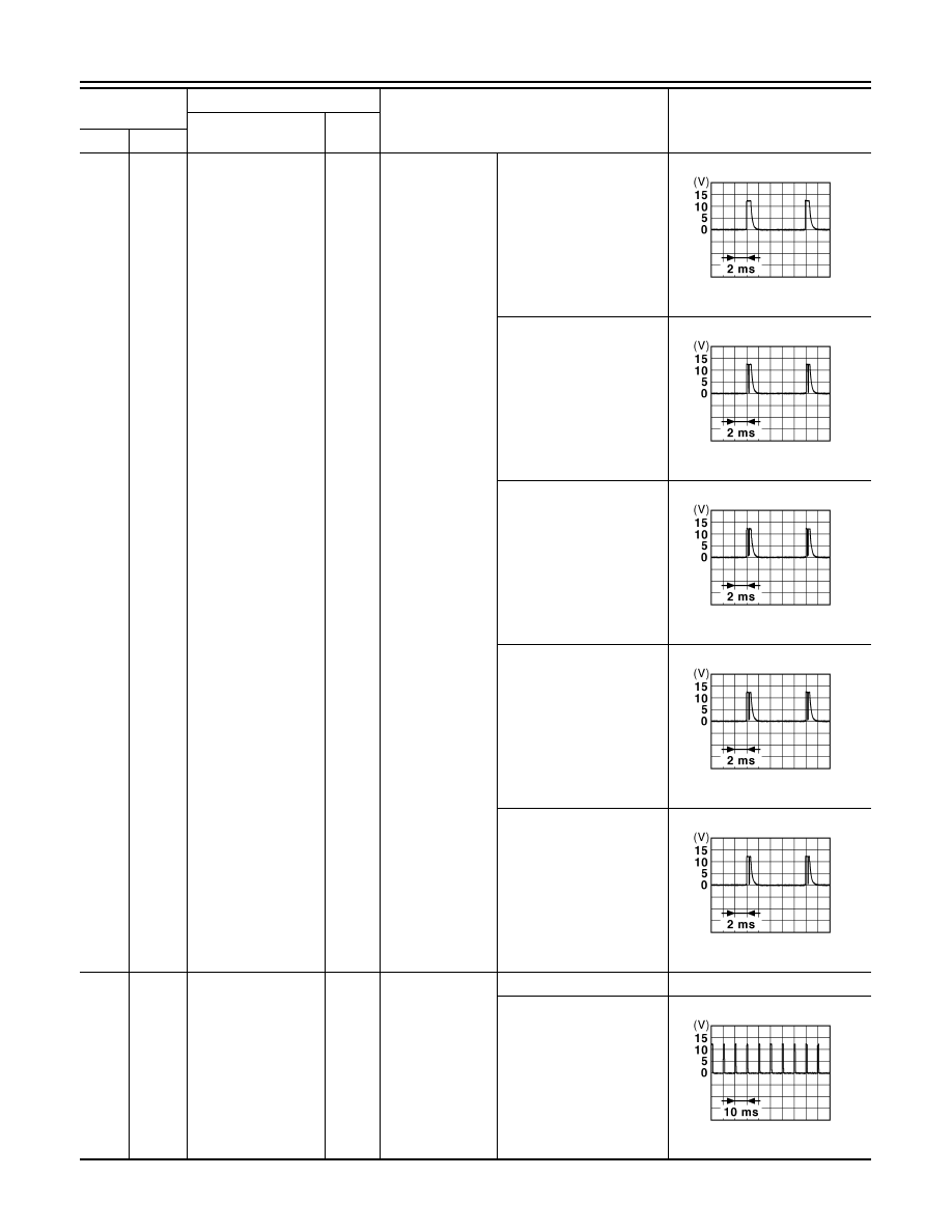
Combination switch
INPUT 2
Input
Combination
switch
(Wiper intermit-
tent dial 4)
All switches OFF
1.4 V
Lighting switch PASS
1.3 V
Lighting switch 2ND
1.3 V
Front wiper switch INT/
AUTO
1.3 V
Front wiper switch HI
1.3 V
110
(G)
Ground
Hazard switch
Input
Hazard switch
ON
0 V
OFF
1.1 V
Terminal No.
(Wire color)
Description
Condition
Value
(Approx.)
Signal name
Input/
Output
+
–
JPMIA0041GB
JPMIA0037GB
JPMIA0036GB
JPMIA0038GB
JPMIA0040GB
JPMIA0012GB
Нет комментариевНе стесняйтесь поделиться с нами вашим ценным мнением.
Текст