Infiniti FX35, FX50 (S51). Manual — part 651

U0101 CAN COMM CIRCUIT
EC-145
< DTC/CIRCUIT DIAGNOSIS >
[VQ35HR]
C
D
E
F
G
H
I
J
K
L
M
A
EC
N
P
O
U0101 CAN COMM CIRCUIT
Description
INFOID:0000000005236738
CAN (Controller Area Network) is a serial communication line for real time application. It is an on-vehicle mul-
tiplex communication line with high data communication speed and excellent error detection ability. Many elec-
tronic control units are equipped onto a vehicle, and each control unit shares information and links with other
control units during operation (not independent). In CAN communication, control units are connected with 2
communication lines (CAN H line, CAN L line) allowing a high rate of information transmission with less wiring.
Each control unit transmits/receives data but selectively reads required data only.
DTC Logic
INFOID:0000000005236739
DTC DETECTION LOGIC
DTC CONFIRMATION PROCEDURE
1.
PERFORM DTC CONFIRMATION PROCEDURE
1.
Turn ignition switch ON and wait at least 3 seconds.
2.
Check DTC.
Is DTC detected?
YES
>>
.
NO
>> INSPECTION END
Diagnosis Procedure
INFOID:0000000005236740
LAN-20, "Trouble Diagnosis Flow Chart"
.
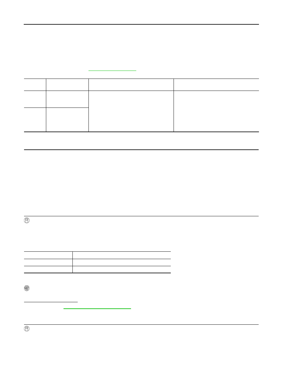
DTC No.
Trouble diagnosis name
DTC detecting condition
Possible cause
U0101
Lost communication
with TCM
When ECM is not transmitting or receiving CAN
communication signal of OBD (emission-related
diagnosis) with TCM for 2 seconds or more.
• CAN communication line between
TCM and ECM
• CAN communication line open or
shorted

EC-146
< DTC/CIRCUIT DIAGNOSIS >
[VQ35HR]
U0164 CAN COMM CIRCUIT
U0164 CAN COMM CIRCUIT
Description
INFOID:0000000005236741
CAN (Controller Area Network) is a serial communication line for real time application. It is an on-vehicle mul-
tiplex communication line with high data communication speed and excellent error detection ability. Many elec-
tronic control units are equipped onto a vehicle, and each control unit shares information and links with other
control units during operation (not independent). In CAN communication, control units are connected with 2
communication lines (CAN H line, CAN L line) allowing a high rate of information transmission with less wiring.
Each control unit transmits/receives data but selectively reads required data only.
DTC Logic
INFOID:0000000005236742
DTC DETECTION LOGIC
DTC CONFIRMATION PROCEDURE
1.
PERFORM DTC CONFIRMATION PROCEDURE
1.
Turn ignition switch ON and wait at least 3 seconds.
2.
Check DTC.
Is DTC detected?
YES
>>
.
NO
>> INSPECTION END
Diagnosis Procedure
INFOID:0000000005236743
Go to
LAN-20, "Trouble Diagnosis Flow Chart"
.
DTC No.
Trouble diagnosis name
DTC detecting condition
Possible cause
U0164
Lost communication
with Unified meter and
A/C amp.
When ECM is not transmitting or receiving CAN com-
munication signal of OBD (emission-related diagno-
sis) with Unified meter and A/C amp. for 2 seconds or
more.
• CAN communication line between
Unified meter and A/C amp. and
ECM
• CAN communication line open or
shorted

U1001 CAN COMM CIRCUIT
EC-147
< DTC/CIRCUIT DIAGNOSIS >
[VQ35HR]
C
D
E
F
G
H
I
J
K
L
M
A
EC
N
P
O
U1001 CAN COMM CIRCUIT
Description
INFOID:0000000005236744
CAN (Controller Area Network) is a serial communication line for real time application. It is an on-vehicle mul-
tiplex communication line with high data communication speed and excellent error detection ability. Many elec-
tronic control units are equipped onto a vehicle, and each control unit shares information and links with other
control units during operation (not independent). In CAN communication, control units are connected with 2
communication lines (CAN H line, CAN L line) allowing a high rate of information transmission with less wiring.
Each control unit transmits/receives data but selectively reads required data only.
DTC Logic
INFOID:0000000005236745
DTC DETECTION LOGIC
DTC CONFIRMATION PROCEDURE
1.
PERFORM DTC CONFIRMATION PROCEDURE
1.
Turn ignition switch ON and wait at least 3 seconds.
2.
Check 1st trip DTC.
Is 1st trip DTC detected?
YES
>>
.
NO
>> INSPECTION END
Diagnosis Procedure
INFOID:0000000005236746
LAN-20, "Trouble Diagnosis Flow Chart"
.
DTC No.
Trouble diagnosis name
DTC detecting condition
Possible cause
U1001
CAN communication line
When ECM is not transmitting or receiving CAN
communication signal other than OBD (emission-
related diagnosis) for 2 seconds or more.
• Harness or connectors
(CAN communication line is open or
shorted)
EC-148
< DTC/CIRCUIT DIAGNOSIS >
[VQ35HR]
P0011, P0021 IVT CONTROL
P0011, P0021 IVT CONTROL
DTC Logic
INFOID:0000000005236747
DTC DETECTION LOGIC
NOTE:
If DTC P0011 or P0021 is displayed with DTC P0075 or P0081, first perform the trouble diagnosis for
DTC P0075, P0081. Refer to
.
DTC CONFIRMATION PROCEDURE
1.
PRECONDITIONING
If DTC Confirmation Procedure has been previously conducted, always perform the following procedure
before conducting the next test.
1.
Turn ignition switch OFF and wait at least 10 seconds.
2.
Turn ignition switch ON.
3.
Turn ignition switch OFF and wait at least 10 seconds.
TESTING CONDITION:
Before performing the following procedure, confirm that battery voltage is between 10 V and 16 V at
idle.
>> GO TO 2.
2.
PERFORM DTC CONFIRMATION PROCEDURE-I
With CONSULT-III
1.
Turn ignition switch ON and select “DATA MONITOR” mode with CONSULT-III.
2.
Start engine and warm it up to the normal operating temperature.
3.
Maintain the following conditions for at least 6 consecutive seconds. Hold the accelerator pedal as steady
as possible.
4.
Let engine idle for 10 seconds.
5.
Check 1st trip DTC.
With GST
Follow the procedure “With CONSULT-III” above.
Is 1st trip DTC detected?
YES
>> Go to
NO
>> GO TO 3.
3.
PERFORM DTC CONFIRMATION PROCEDURE-II
With CONSULT-III
1.
Select “DATA MONITOR” mode with CONSULT-III.
2.
Maintain the following conditions for at least 20 consecutive seconds.
DTC No.
Trouble diagnosis
name
DTC detecting condition
Possible cause
P0011
Intake valve timing
(IVT) control perfor-
mance (bank 1)
There is a gap between angle of target and
phase-control angle degree.
• Crankshaft position sensor
• Camshaft position sensor
• IVT control solenoid valve
• Accumulation of debris to the signal pick-up
portion of the camshaft
• Timing chain installation
• Foreign matter caught in the oil groove for in-
take valve timing control
P0021
Intake valve timing
(IVT) control perfor-
mance (bank 2)
ENG SPEED
1,200 - 2,000 rpm (A constant rotation is maintained)
COOLAN TEMP/S
More than 60
°
C (140
°
F)
Selector lever
P or N position
Нет комментариевНе стесняйтесь поделиться с нами вашим ценным мнением.
Текст