Infiniti FX35, FX50 (S51). Manual — part 1773
RAS SYSTEM
STC-33
< SYSTEM DESCRIPTION >
[WITH REAR ACTIVE STEER]
C
D
E
F
H
I
J
K
L
M
A
B
STC
N
O
P
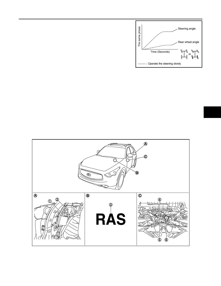
• The rear wheels turn to the same phase of front wheels when turn-
ing the steering wheel slowly.
During extremely slow-speed driving and at straight-ahead driving
• The rear wheels do not turn during extremely slow-speed driving regardless of the operation speed of steer-
ing wheel.
• The rear wheels do not turn at straight-ahead driving regardless of the vehicle speed.
OPERATION FEATURE
RAS ACTUATOR
• It is driven by RAS motor.
• The irreversible efficiency performance hypoid gear secures the toe-stiffness of rear wheels against the road
external force and keep the steering angle when system is malfunction.
• The power from the pinion gear (motor side) is transmitted, but the pinion gear does not rotate as caused by
the gear mechanical characteristics (teeth angle) even though the ring gear (tire side) starts to rotate.
Component Parts Location
INFOID:0000000005235358
SGIA1442E
1.
RAS control unit
2.
RAS motor relay
3.
RAS warning lamp
4.
RAS rear motor
5.
RAS rear actuator
6.
Rear wheel steering angle sensor
A.
Inside the rear wheel house finisher
(left)
B.
Inside combination meter
C.
RAS rear actuator assembly
JSGIA0770ZZ

STC-34
< SYSTEM DESCRIPTION >
[WITH REAR ACTIVE STEER]
RAS SYSTEM
Component Description
INFOID:0000000005235359
Component parts
Reference/Function
Steering angle sensor
RAS control unit
RAS actuator
The rear wheel steering angle is activated.
Rear wheel steering angle sensor
RAS motor
ABS actuator and electronic unit (con-
trol unit)
ECM
Power steering solenoid valve
RAS warning lamp
Stop lamp switch
This switch is used for self-diagnosis without CONSULT-III.

EPS SYSTEM
STC-35
< SYSTEM DESCRIPTION >
[WITH REAR ACTIVE STEER]
C
D
E
F
H
I
J
K
L
M
A
B
STC
N
O
P
EPS SYSTEM
System Diagram
INFOID:0000000005235360
CONTROL DIAGRAM
CROSS-SECTIONAL VIEW
System Description
INFOID:0000000005235361
• The EPS system controls the power steering solenoid valve through the RAS control unit.
JSGIA0416GB
1.
Unified meter and A/C amp.
2.
RAS control unit
3.
Power steering solenoid valve
4.
Steering gear assembly
5.
Gear housing assembly
6.
Gear sub-assembly
7.
Pinion
8.
Power steering oil pump
9.
Reservoir tank
JSGIA0376ZZ
STC-36
< SYSTEM DESCRIPTION >
[WITH REAR ACTIVE STEER]
EPS SYSTEM
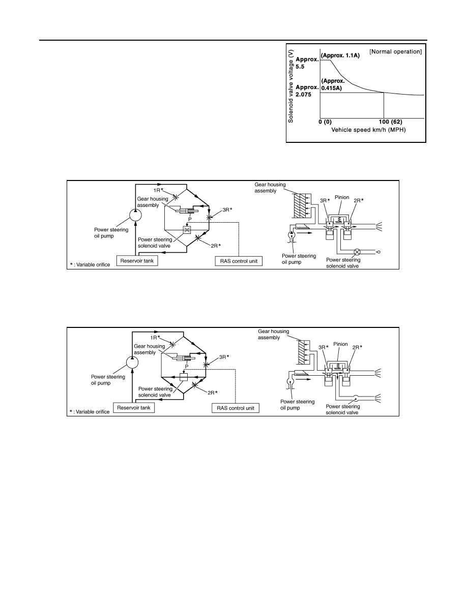
• The valve driving voltage to control the power steering solenoid
valve varies according to the vehicle speed.
OPERATION PRINCIPLE
During Parking (When Turning The Steering Wheel To The Right.)
1.
Power steering solenoid valve is closed while a vehicle is stopped.
2.
Pinion “1R”, “2R” and “3R” are closed depending on steering torque of steering wheel.
3.
Oil pressure “P” in the gear housing assembly is the sum of oil pressures occurred in “2R” and “3R”. This
results in a light steering force because of high pressure.
During High-speed Operation
1.
Power steering solenoid valve is opened during high-speed operation.
2.
Pinion “1R”, “2R” and “3R” are closed depending on steering torque of steering wheel.
3.
Oil pressure “2R” does not occur because the power steering solenoid valve is on full throttle.
4.
Oil pressure “P” in the gear housing assembly includes only oil pressure occurred in “3R” and results in a
heavy steering force.
JSGIA0451GB
SGIA1583E
SGIA1584E
Нет комментариевНе стесняйтесь поделиться с нами вашим ценным мнением.
Текст