Infiniti FX35, FX50 (S51). Manual — part 1792
RAS CONTROL UNIT
STC-109
< REMOVAL AND INSTALLATION >
[WITH REAR ACTIVE STEER]
C
D
E
F
H
I
J
K
L
M
A
B
STC
N
O
P
REMOVAL AND INSTALLATION
RAS CONTROL UNIT
Removal and Installation
INFOID:0000000005235470
REMOVAL
1.
Turn the ignition switch OFF.
2.
Remove the luggage side finisher lower (LH). Refer to
.
3.
Remove E-SUS control unit. Refer to
.
4.
Disconnect the RAS control unit connector and harness clip.
5.
Remove the RAS control unit mounting bolts.
6.
Remove the RAS control unit.
INSTALLATION
Install in the reverse order of removal.
STC-110
< REMOVAL AND INSTALLATION >
[WITH REAR ACTIVE STEER]
REAR ACTIVE STEER
REAR ACTIVE STEER
Exploded View
INFOID:0000000005235471
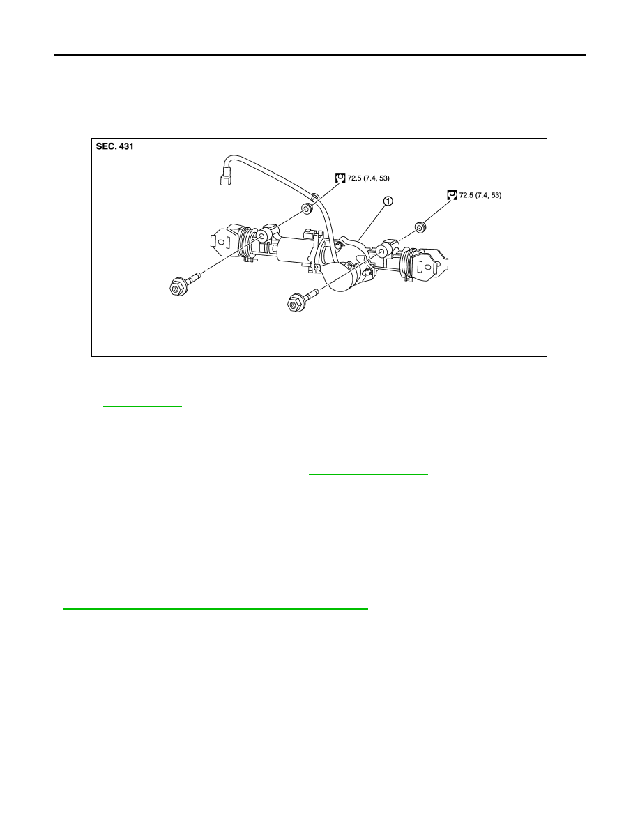
COMPONENTS
Removal and Installation
INFOID:0000000005235472
REMOVAL
1.
Remove coil spring and rear lower link. Refer to
2.
Disconnect harness connector from RAS actuator assembly and rear suspension member.
3.
Remove fixing bolts and nuts of RAS actuator assembly, and then remove RAS actuator assembly from
rear suspension member.
INSTALLATION
Note the following, and install in the reverse order of removal.
• When installing RAS actuator assembly to rear suspension member, check the mounting surfaces of RAS
actuator assembly and rear suspension member for oil, dirt, sand, or other foreign materials.
• Check rear wheel alignment. Refer to
.
• Adjust neutral position of steering angle sensor. Refer to
BRC-9, "ADJUSTMENT OF STEERING ANGLE
SENSOR NEUTRAL POSITION : Special Repair Requirement"
.
1.
RAS actuator assembly
Refer to
, for the symbols in the figure.
JSGIA0473GB
STR-1
ENGINE
C
D
E
F
G
H
I
J
K
L
M
SECTION
STR
A
STR
N
O
P
CONTENTS
STARTING SYSTEM
BASIC INSPECTION . . . . . . . . .
DIAGNOSIS AND REPAIR WORKFLOW . . ..
Work Flow . . . . . . . . . . . . . . . .....
SYSTEM DESCRIPTION . . . . . . . ..
STARTING SYSTEM . . . . . . . . . . ...
System Diagram . . . . . . . . . . . . . ....
System Description . . . . . . . . . . . . ...
VQ35HR . . . . . . . . . . . . . . . . . ...
VQ35HR : Component Parts Location . . . . . ..
VK50VE . . . . . . . . . . . . . . . . . ...
VK50VE : Component Parts Location . . . . . ...
Component Description . . . . . . . . . . ....
DTC/CIRCUIT DIAGNOSIS . . . . . . ..
B TERMINAL CIRCUIT . . . . . . . . . ...
Description . . . . . . . . . . . . . . . ....
Diagnosis Procedure . . . . . . . . . . . .....
S CONNECTOR CIRCUIT . . . . . . . . ...
Description . . . . . . . . . . . . . . . ....
Diagnosis Procedure . . . . . . . . . . . .....
STARTING SYSTEM . . . . . . . . . . ..
Wiring Diagram - STARTING SYSTEM - . . . .
SYMPTOM DIAGNOSIS . . . . . . . ..
STARTING SYSTEM . . . . . . . . . . ..
Symptom Table . . . . . . . . . . . . . ...
PRECAUTION . . . . . . . . . . . ..
PRECAUTIONS . . . . . . . . . . . . .
PREPARATION . . . . . . . . . . ...
PREPARATION . . . . . . . . . . . . .
Special Service Tools . . . . . . . . . . . ..
Commercial Service Tools . . . . . . . . . ...
REMOVAL AND INSTALLATION . . . ...
STARTER MOTOR . . . . . . . . . . ...
VQ35HR . . . . . . . . . . . . . . . . . .
VQ35HR : Exploded View . . . . . . . . . ...
VQ35HR : Removal and Installation (2WD) . . .
VQ35HR : Removal and Installation (AWD) . . .
VQ35HR : Inspection . . . . . . . . . . . ...
VK50VE . . . . . . . . . . . . . . . . . ..
VK50VE : Exploded View . . . . . . . . . .
VK50VE : Removal and Installation . . . . . . .
VK50VE : Inspection . . . . . . . . . . . .
SERVICE DATA AND SPECIFICATIONS
(SDS) . . . . . . . . . . . . . . .
SERVICE DATA AND SPECIFICATIONS
(SDS) . . . . . . . . . . . . . . . . .
STR-2
< BASIC INSPECTION >
DIAGNOSIS AND REPAIR WORKFLOW
BASIC INSPECTION
DIAGNOSIS AND REPAIR WORKFLOW
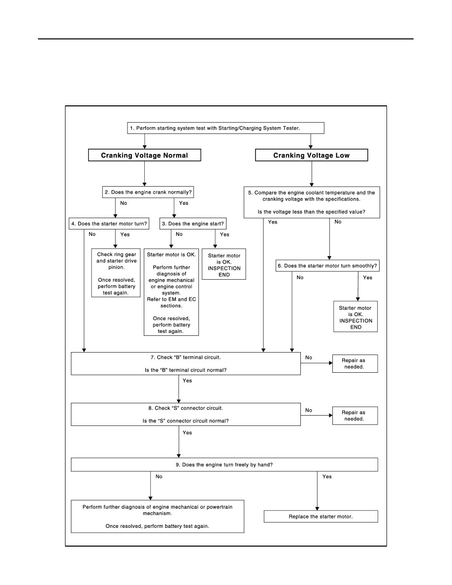
Work Flow
INFOID:0000000005245519
OVERALL SEQUENCE
DETAILED FLOW
JSBIA0022GB
Нет комментариевНе стесняйтесь поделиться с нами вашим ценным мнением.
Текст