Infiniti FX35, FX50 (S51). Manual — part 1550
PWO-10
< PRECAUTION >
PRECAUTIONS
PRECAUTION
PRECAUTIONS
Precaution for Supplemental Restraint System (SRS) "AIR BAG" and "SEAT BELT
PRE-TENSIONER"
INFOID:0000000005240724
The Supplemental Restraint System such as “AIR BAG” and “SEAT BELT PRE-TENSIONER”, used along
with a front seat belt, helps to reduce the risk or severity of injury to the driver and front passenger for certain
types of collision. This system includes seat belt switch inputs and dual stage front air bag modules. The SRS
system uses the seat belt switches to determine the front air bag deployment, and may only deploy one front
air bag, depending on the severity of a collision and whether the front occupants are belted or unbelted.
Information necessary to service the system safely is included in the “SRS AIR BAG” and “SEAT BELT” of this
Service Manual.
WARNING:
• To avoid rendering the SRS inoperative, which could increase the risk of personal injury or death in
the event of a collision which would result in air bag inflation, all maintenance must be performed by
an authorized NISSAN/INFINITI dealer.
• Improper maintenance, including incorrect removal and installation of the SRS, can lead to personal
injury caused by unintentional activation of the system. For removal of Spiral Cable and Air Bag
Module, see the “SRS AIR BAG”.
• Do not use electrical test equipment on any circuit related to the SRS unless instructed to in this
Service Manual. SRS wiring harnesses can be identified by yellow and/or orange harnesses or har-
ness connectors.
PRECAUTIONS WHEN USING POWER TOOLS (AIR OR ELECTRIC) AND HAMMERS
WARNING:
• When working near the Air Bag Diagnosis Sensor Unit or other Air Bag System sensors with the
ignition ON or engine running, DO NOT use air or electric power tools or strike near the sensor(s)
with a hammer. Heavy vibration could activate the sensor(s) and deploy the air bag(s), possibly
causing serious injury.
• When using air or electric power tools or hammers, always switch the ignition OFF, disconnect the
battery, and wait at least 3 minutes before performing any service.
PWO
POWER SOCKET
PWO-11
< REMOVAL AND INSTALLATION >
C
D
E
F
G
H
I
J
K
L
B
A
O
P
N
REMOVAL AND INSTALLATION
POWER SOCKET
FRONT POWER SOCKET
FRONT POWER SOCKET : Exploded View
INFOID:0000000005240725
FRONT POWER SOCKET : Removal and Installation
INFOID:0000000005240726
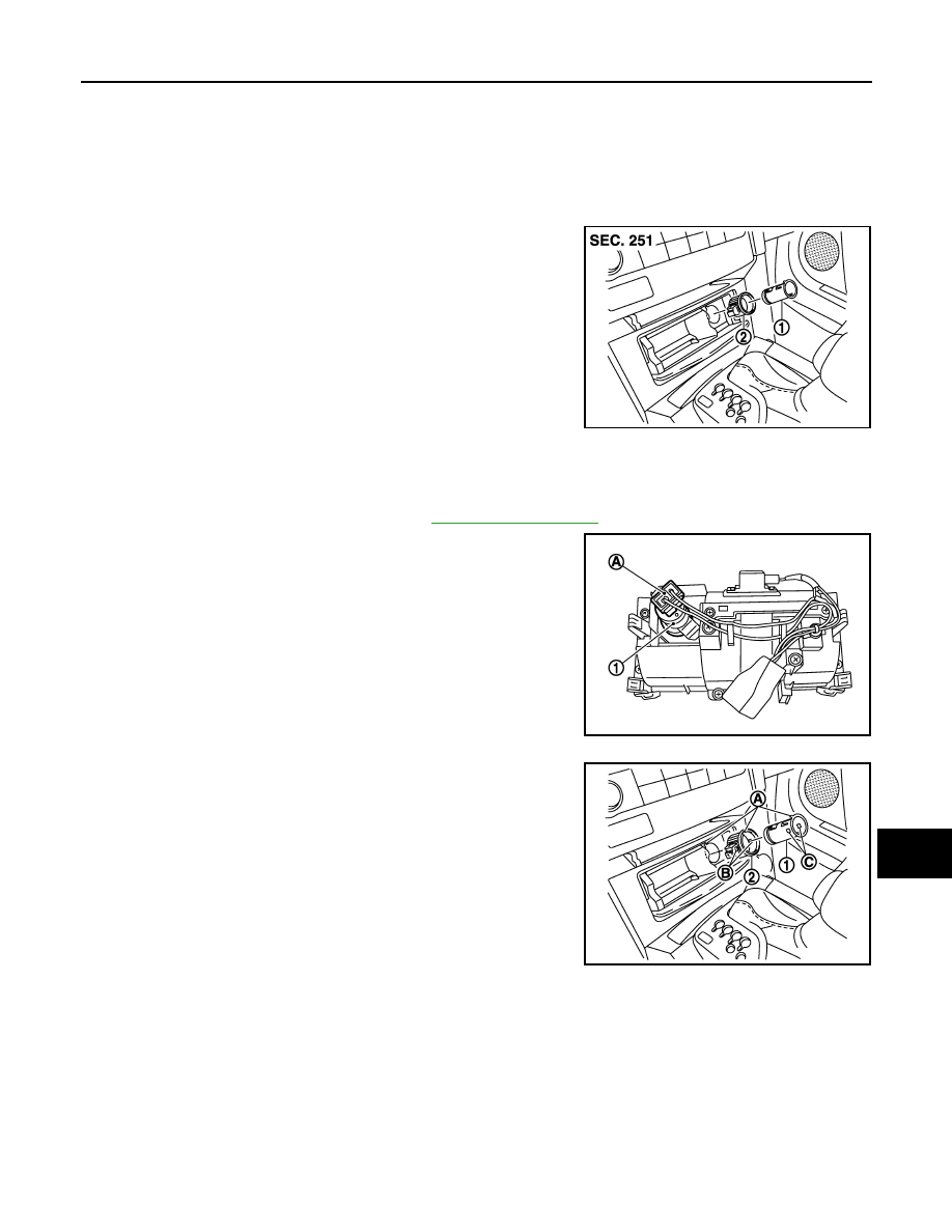
REMOVAL
1.
Remove console pocket assembly. Refer to
2.
Disconnect power socket connector (A) from reverse side inner
socket (1).
3.
Pull out inner socket (1) by pushing the ring pawl (B) from the
inner socket hole (square) (C).
4.
Remove ring (2) from console pocket assembly while pressing
pawls.
INSTALLATION
Install in the reverse order of removal.
NOTE:
Align the cut outs of inner socket, ring, and console pocket assembly.
CONSOLE POWER SOCKET
1
: Inner socket
2
: Ring
JPMIA1053ZZ
JPMIA1054ZZ
A
: Cut out
JPMIA1055ZZ
PWO-12
< REMOVAL AND INSTALLATION >
POWER SOCKET
CONSOLE POWER SOCKET : Exploded View
INFOID:0000000005240727
CONSOLE POWER SOCKET : Removal and Installation
INFOID:0000000005240728
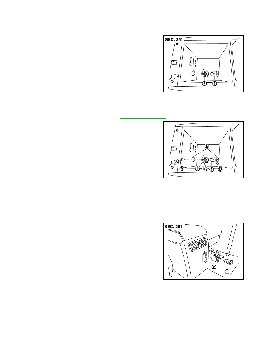
REMOVAL
1.
Remove center console assembly. Refer to
.
2.
Disconnect power socket connector (A).
3.
Pull out inner socket (1) by pushing the ring pawl (C) from the
inner socket hole (square) (D).
4.
Remove ring (2) from console box assembly while pressing
pawls.
INSTALLATION
Install in the reverse order of removal.
NOTE:
Align the cut outs of inner socket, ring, and console box assembly.
REAR POWER SOCKET
REAR POWER SOCKET : Exploded View
INFOID:0000000005240729
REAR POWER SOCKET : Removal and Installation
INFOID:0000000005240730
REMOVAL
1.
Remove console rear finisher. Refer to
.
1
: Inner socket
2
: Ring
JPMIA1056ZZ
B
: Cut out
JPMIA1057ZZ
1
: Inner socket
2
: Ring
JPMIA1058ZZ
PWO
POWER SOCKET
PWO-13
< REMOVAL AND INSTALLATION >
C
D
E
F
G
H
I
J
K
L
B
A
O
P
N
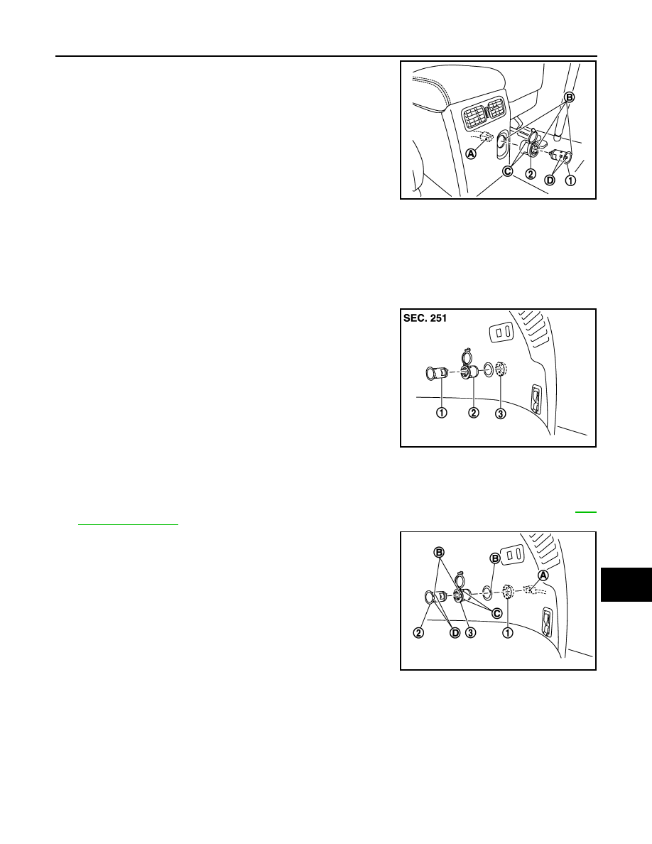
2.
Disconnect power socket connector (A).
3.
Pull out inner socket (1) by pushing the ring pawl (C) from the
inner socket hole (square) (D).
4.
Remove ring (2) from console rear finisher while pressing pawls.
INSTALLATION
Install in the reverse order of removal.
NOTE:
Align the cut outs of inner socket, ring, and console rear finisher.
LUGGAGE ROOM POWER SOCKET
LUGGAGE ROOM POWER SOCKET : Exploded View
INFOID:0000000005240731
LUGGAGE ROOM POWER SOCKET : Removal and Installation
INFOID:0000000005240732
REMOVAL
1.
Remove clips on the back of the luggage side finisher lower (RH) to obtain space for work. Refer to
2.
Disconnect power socket connector (A).
3.
Remove retainer (1) and remove power socket assembly.
4.
Pull out inner socket (2) by pushing the ring pawl (C) from the
inner socket hole (square) (D).
5.
Remove ring (3) from luggage side finisher lower (RH) while
pressing pawls.
INSTALLATION
Install in the reverse order of removal.
NOTE:
Align the cut outs of inner socket, ring, and luggage side finisher lower (RH).
B
: Cut out
JPMIA1059ZZ
1
: Inner socket
2
: Ring
3
: Retainer
JPMIA1060ZZ
B
: Cut out
JPMIA1061ZZ
Нет комментариевНе стесняйтесь поделиться с нами вашим ценным мнением.
Текст