Infiniti FX35, FX50 (S51). Manual — part 585
DRIVE PINION
DLN-175
< UNIT DISASSEMBLY AND ASSEMBLY >
[FRONT FINAL DRIVE: F160A]
C
E
F
G
H
I
J
K
L
M
A
B
DLN
N
O
P
Disassembly
INFOID:0000000005249207
1.
Remove differential case assembly. Refer to
2.
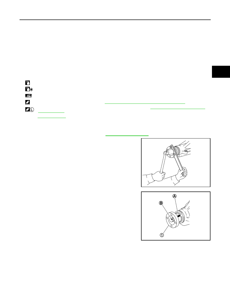
Remove drive pinion lock nut with a flange wrench.
3.
Put matching mark (B) on the end of drive pinion. The matching
mark should be in line with the matching mark (A) on companion
flange (1).
CAUTION:
For matching mark, use paint. Never damage companion
flange and drive pinion.
NOTE:
The matching mark (A) on the final drive companion flange (1)
indicates the maximum vertical runout position.
When replacing companion flange, matching mark is not neces-
sary.
10. Drive pinion
11.
Drive gear
12. Side oil seal (right side)
13. Side retainer
14. O-ring
15. Side bearing adjusting shim
16. Side bearing
17. Differential case
18. Breather connector
19. Dowel pin
20. Filler plug
21. Drain plug
22. Gasket
23. Carrier cover
24. Gear oil defense
25. Side gear thrust washer
26. Side gear
27. Circular clip
28. Pinion mate thrust washer
29. Pinion mate gear
30. Pinion mate shaft
31. Lock pin
32. Side bearing adjusting washer
33. Side oil seal (left side)
34. Side shaft bearing
35. Extension tube retainer
36. Side shaft oil seal
37. Dust seal
38. Side shaft
A:
Oil seal lip
B:
Screw hole
: Apply gear oil.
: Apply anti-corrosion oil.
: Apply multi-purpose grease.
: Apply Genuine Silicone RTV or equivalent. Refer to
GI-16, "Recommended Chemical Products and Sealants"
.
:
Apply Genuine Medium Strength Thread Locking Sealant or equivalent. Refer to
GI-16, "Recommended Chemical Prod-
.
Refer to
for symbols not described above.
PDIA0798J
PDIA0799J
DLN-176
< UNIT DISASSEMBLY AND ASSEMBLY >
[FRONT FINAL DRIVE: F160A]
DRIVE PINION
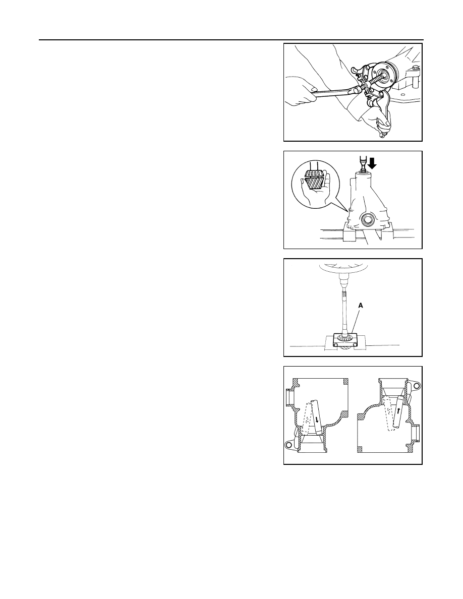
4.
Remove companion flange using the suitable puller.
5.
Press drive pinion assembly out of gear carrier.
CAUTION:
Never drop drive pinion assembly.
6.
Remove front oil seal.
7.
Remove pinion front bearing inner race.
8.
Remove drive pinion bearing adjusting washer and drive pinion
adjusting washer.
9.
Remove pinion rear bearing inner race and pinion height adjust-
ing washer with replacer (A) (commercial service tool).
10. Tap pinion front/rear bearing outer races uniformly a brass rod or
equivalent to removed.
CAUTION:
Never damage gear carrier.
SDIA1132E
PDIA0800J
PDIA0801J
PDIA0677E
DRIVE PINION
DLN-177
< UNIT DISASSEMBLY AND ASSEMBLY >
[FRONT FINAL DRIVE: F160A]
C
E
F
G
H
I
J
K
L
M
A
B
DLN
N
O
P
Assembly
INFOID:0000000005249208
1.
Install pinion front and rear bearing outer races using drift (A)
[SST: ST37820000 (
—
)].
CAUTION:
• At first, using a hammer, tap bearing outer race until it
becomes flat to gear carrier.
• Never reuse pinion front and rear bearing outer race.
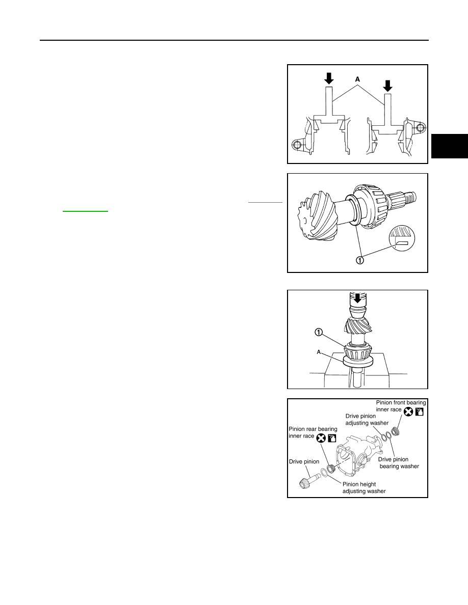
2.
Temporarily install pinion height adjusting washer (1).
When hypoid gear set has been replaced
• Select pinion height adjusting washer. Refer to
.
When hypoid gear set has been reused
• Temporarily install the removed pinion height adjusting washer
or same thickness washer to drive pinion.
CAUTION:
• Pay attention to the direction of pinion height adjusting
washer. (Assemble as shown in the figure.)
• Never reuse pinion rear bearing inner race.
3.
Install pinion rear bearing inner race (1) to drive pinion with the
drift (A) [SST: ST30032000 (J-26010-01)].
4.
Temporarily assemble removed drive pinion adjusting washer
and drive pinion bearing adjusting washer or same thickness of
them to drive pinion.
5.
Apply gear oil to pinion rear bearing, and assemble drive pinion
into gear carrier.
6.
Apply gear oil to pinion front bearing, and assemble pinion front
bearing inner race to drive pinion assembly.
CAUTION:
Never reuse pinion front bearing inner race.
PDIA0803J
JSDIA0760ZZ
JSDIA0761ZZ
PDIA0681E
DLN-178
< UNIT DISASSEMBLY AND ASSEMBLY >
[FRONT FINAL DRIVE: F160A]
DRIVE PINION
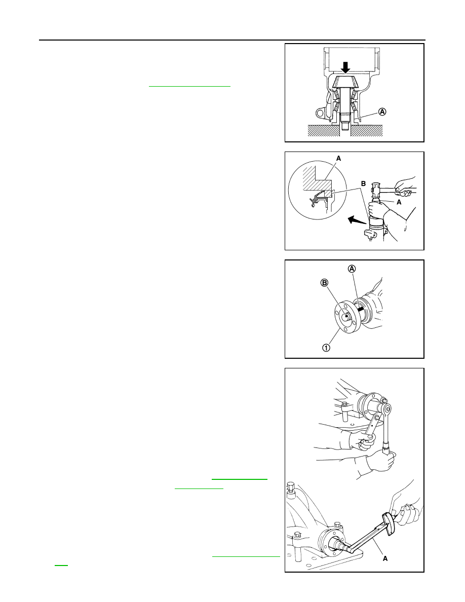
7.
Using suitable spacer (A), press the pinion front bearing inner
race to drive pinion as far as drive pinion nut can be tightened.
8.
Adjust pinion bearing preload. If necessary, select the appropri-
ate drive pinion adjusting washer and drive pinion bearing
adjusting washer. Refer to
.
9.
Using the drifts, install front oil seal as shown in figure.
CAUTION:
• Never reuse oil seal.
• When installing, never incline oil seal.
• Apply multi-purpose grease onto oil seal lips, and gear oil
onto the circumference of oil seal.
10. Install companion flange (1).
NOTE:
When reusing drive pinion, align the matching mark (B) of drive
pinion with the matching mark (A) of companion flange, and then
install companion flange (1).
11. Apply anti-corrosion oil to the thread and seat of new drive pin-
ion lock nut, and temporarily tighten drive pinion lock nut to drive
pinion.
CAUTION:
Never reuse drive pinion lock nut.
12. Tighten to drive pinion lock nut, while adjusting pinion bearing
preload torque.
CAUTION:
• Adjust to the lower limit of the drive pinion lock nut tight-
ening torque first.
• After adjustment, rotate drive pinion back and forth 2 to 3
times to check for unusual noise, rotation malfunction,
and other malfunctions.
13. Install differential case assembly. Refer to
CAUTION:
PDIA0807J
A: Drift [SST: ST33400001 (J-26082)]
B: Drift [SST: KV38102510 (
—
)]
PDIA0808J
PDIA0799J
A: Preload gauge [SST: ST3127S000 (J-25765-A)]
Standard
Pinion bearing preload
: Refer to
PDIA0802J
Нет комментариевНе стесняйтесь поделиться с нами вашим ценным мнением.
Текст