Infiniti FX35, FX50 (S51). Manual — part 728

P2138 APP SENSOR
EC-453
< DTC/CIRCUIT DIAGNOSIS >
[VQ35HR]
C
D
E
F
G
H
I
J
K
L
M
A
EC
N
P
O
2.
Disconnect ECM harness connector.
3.
Check the continuity between APP sensor harness connector and ECM harness connector.
Is the inspection result normal?
YES
>> GO TO 7.
NO
>> GO TO 6.
6.
DETECT MALFUNCTIONING PART
Check the following.
• Harness connectors M6, E106
• Harness for open between ECM and APP sensor
>> Repair open circuit.
7.
CHECK SENSOR POWER SUPPLY CIRCUIT
Check harness for short to power and short to ground, between the following terminals.
Is the inspection result normal?
YES
>> GO TO 8.
NO
>> Repair short to ground or short to power in harness or connectors.
8.
CHECK COMPONENTS
Check the following.
• CKP sensor (Refer to
EC-271, "Component Inspection"
• CMP sensor (bank 2) (Refer to
EC-277, "Component Inspection"
.)
• EVT control position sensor (bank 2) (Refer to
EC-369, "Component Inspection"
• Battery current sensor (Refer to
EC-400, "Component Inspection"
.)
• EVAP control system pressure sensor (Refer to
EC-313, "Component Inspection"
.)
• Refrigerant pressure sensor (Refer to
Is the inspection result normal?
YES
>> GO TO 15.
NO
>> Replace malfunctioning component.
9.
CHECK APP SENSOR GROUND CIRCUIT FOR OPEN AND SHORT
1.
Turn ignition switch OFF.
APP sensor
ECM
Continuity
Connector
Terminal
Connector
Terminal
E112
(Without ICC)
6
M107
103
Existed
E116
(With ICC)
3
ECM
Sensor
Connector
Terminal
Name
Connector
Terminal
F101
46
Crankshaft position (CKP) sensor
F2
1
F102
64
Camshaft position (CMP) sensor (bank 2)
F18
1
Exhaust valve timing (EVT) control posi-
tion sensor (bank 2)
F19
1
Battery current sensor
E21
1
M107
103
APP sensor
E112
(Without ICC)
6
E116
(With ICC)
3
107
EVAP control system pressure sensor
B252
3
111
Refrigerant pressure sensor
E77
3

EC-454
< DTC/CIRCUIT DIAGNOSIS >
[VQ35HR]
P2138 APP SENSOR
2.
Disconnect ECM harness connector.
3.
Check the continuity between APP sensor harness connector and ECM harness connector.
4.
Also check harness for short to ground and short to power.
Is the inspection result normal?
YES
>> GO TO 11.
NO
>> GO TO 10.
10.
DETECT MALFUNCTIONING PART
Check the following.
• Harness connectors M6, E106
• Harness for open or short between ECM and APP sensor
>> Repair open circuit, short to ground or short to power in harness or connectors.
11.
CHECK APP SENSOR INPUT SIGNAL CIRCUIT FOR OPEN AND SHORT
1.
Check the continuity between APP sensor harness connector and ECM harness connector.
2.
Also check harness for short to ground and short to power.
Is the inspection result normal?
YES
>> GO TO 13.
NO
>> GO TO 12.
12.
DETECT MALFUNCTIONING PART
Check the following.
• Harness connectors M6, E106
• Harness for open or short between ECM and APP sensor
>> Repair open circuit, short to ground or short to power in harness or connectors.
13.
CHECK APP SENSOR
EC-455, "Component Inspection"
Is the inspection result normal?
YES
>> GO TO 15.
NO
>> GO TO 14.
14.
REPLACE ACCELERATOR PEDAL ASSEMBLY
1.
Replace accelerator pedal assembly.
2.
Go to
EC-455, "Special Repair Requirement"
.
>> INSPECTION END
APP sensor
ECM
Continuity
Connector
Terminal
Connector
Terminal
E112
(Without ICC)
4
M107
100
Existed
2
104
E116
(With ICC)
1
100
2
104
APP sensor
ECM
Continuity
Connector
Terminal
Connector
Terminal
E112
(Without ICC)
3
M107
97
Existed
1
98
E116
(With ICC)
4
97
6
98

P2138 APP SENSOR
EC-455
< DTC/CIRCUIT DIAGNOSIS >
[VQ35HR]
C
D
E
F
G
H
I
J
K
L
M
A
EC
N
P
O
15.
CHECK INTERMITTENT INCIDENT
GI-36, "Intermittent Incident"
.
>> INSPECTION END
Component Inspection
INFOID:0000000005237064
1.
CHECK ACCELERATOR PEDAL POSITION (APP) SENSOR
1.
Turn ignition switch OFF.
2.
Reconnect all harness connectors disconnected.
3.
Turn ignition switch ON.
4.
Check the voltage ECM harness connector terminals under the following conditions.
Is the inspection result normal?
YES
>> INSPECTION END
NO
>> GO TO 2.
2.
REPLACE ACCELERATOR PEDAL ASSEMBLY
1.
Replace accelerator pedal assembly.
2.
Go to
EC-455, "Special Repair Requirement"
.
>> INSPECTION END
Special Repair Requirement
INFOID:0000000005237065
1.
PERFORM ACCELERATOR PEDAL RELEASED POSITION LEARNING
Refer to
EC-25, "ACCELERATOR PEDAL RELEASED POSITION LEARNING : Special Repair Requirement"
.
>> GO TO 2.
2.
PERFORM THROTTLE VALVE CLOSED POSITION LEARNING
EC-25, "THROTTLE VALVE CLOSED POSITION LEARNING : Special Repair Requirement"
>> GO TO 3.
3.
PERFORM IDLE AIR VOLUME LEARNING
EC-25, "IDLE AIR VOLUME LEARNING : Special Repair Requirement"
>> END
ECM
Condition
Voltage (V)
Connector
+
–
Terminal
Terminal
M107
97 (APP sensor 1)
100
Accelerator pedal
Fully released
0.45 - 1.0
Fully depressed
4.4 - 4.8
98 (APP sensor 2)
104
Fully released
0.22 - 0.50
Fully depressed
2.1 - 2.5
EC-456
< DTC/CIRCUIT DIAGNOSIS >
[VQ35HR]
P2A00, P2A03 A/F SENSOR 1
P2A00, P2A03 A/F SENSOR 1
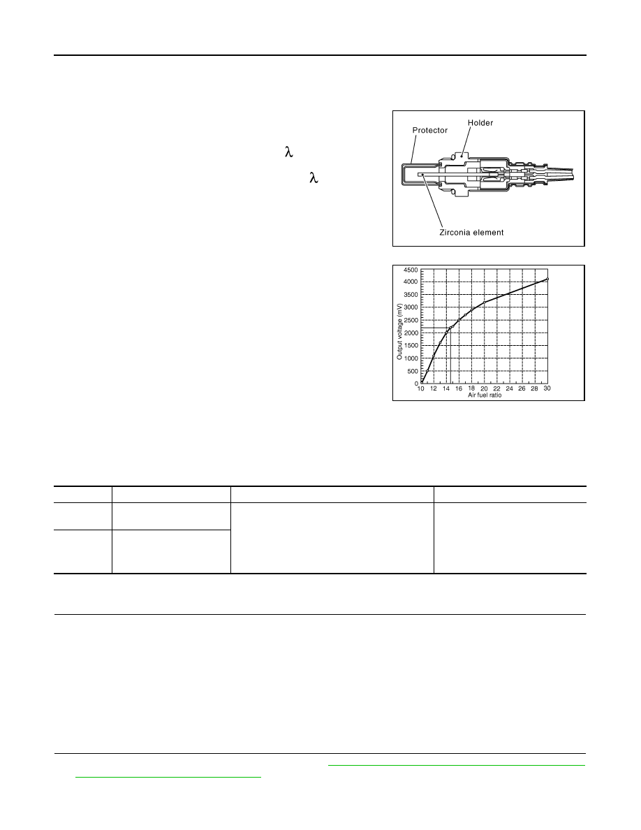
Description
INFOID:0000000005237066
The air fuel ratio (A/F) sensor 1 is a planar one-cell limit current sen-
sor. The sensor element of the A/F sensor 1 is composed an elec-
trode layer, which transports ions. It has a heater in the element.
The sensor is capable of precise measurement = 1, but also in the
lean and rich range. Together with its control electronics, the sensor
outputs a clear, continuous signal throughout a wide range.
The exhaust gas components diffuse through the diffusion layer at
the sensor cell. An electrode layer is applied voltage, and this current
relative oxygen density in lean. Also this current relative hydrocar-
bon density in rich.
Therefore, the A/F sensor 1 is able to indicate air fuel ratio by this
electrode layer of current. In addition, a heater is integrated in the
sensor to ensure the required operating temperature of approxi-
mately 800
°
C (1,472
°
F).
DTC Logic
INFOID:0000000005237067
DTC DETECTION LOGIC
To judge the malfunction, the air fuel ratio (A/F) signal computed by ECM from the A/F sensor 1 signal is mon-
itored so it will not shift to LEAN side or RICH side.
DTC CONFIRMATION PROCEDURE
1.
PRECONDITIONING
If DTC Confirmation Procedure has been previously conducted, always perform the following procedure
before conducting the next test.
1.
Turn ignition switch OFF and wait at least 10 seconds.
2.
Turn ignition switch ON.
3.
Turn ignition switch OFF and wait at least 10 seconds.
TESTING CONDITION:
Before performing the following procedure, confirm that battery voltage is more than 11 V at idle.
>> GO TO 2.
2.
PERFORM DTC CONFIRMATION PROCEDURE
1.
Clear the mixture ratio self-learning value. Refer to
EC-28, "MIXTURE RATIO SELF-LEARNING VALUE
CLEAR : Special Repair Requirement"
.
2.
Turn ignition switch OFF and wait at least 10 seconds.
JMBIA0112GB
PBIB3354E
DTC No.
Trouble diagnosis name
DTC detecting condition
Possible cause
P2A00
A/F sensor 1 (bank 1) circuit
range/performance
• The output voltage computed by ECM from the
A/F sensor 1 signal shifts to the lean side for a
specified period.
• The A/F signal computed by ECM from the A/F
sensor 1 signal shifts to the rich side for a spec-
ified period.
• A/F sensor 1
• A/F sensor 1 heater
• Fuel pressure
• Fuel injector
• Intake air leaks
P2A03
A/F sensor 1 (bank 2) circuit
range/performance
Нет комментариевНе стесняйтесь поделиться с нами вашим ценным мнением.
Текст