Infiniti FX35, FX50 (S51). Manual — part 1778
C1911, C1912 RAS MOTOR POWER SUPPLY
STC-53
< DTC/CIRCUIT DIAGNOSIS >
[WITH REAR ACTIVE STEER]
C
D
E
F
H
I
J
K
L
M
A
B
STC
N
O
P
• Open between the ignition switch and RAS control unit harness connector No. 27 terminal
• Ignition switch
2.
CHECK RAS MOTOR POWER SUPPLY CIRCUIT (1)
1.
Turn the ignition switch OFF.
2.
Remove RAS motor relay.
3.
Check the continuity between RAS motor relay harness connector and ground.
4.
Check the continuity between RAS motor relay harness connector and RAS control unit harness connec-
tor.
Is the inspection result normal?
YES
>> GO TO 3.
NO
>> Repair or replace the harnesses and connectors.
3.
CHECK RAS MOTOR POWER SUPPLY CIRCUIT (2)
Check the voltage between RAS motor relay harness connector and ground.
Is the inspection result normal?
YES
>> GO TO 4.
NO
>>
Check the following items. Repair or replace the malfunctioning parts.
• 20A fuse (#37) open
- Short among 20A fuse (#37) connector, RAS motor relay harness connector No. 3 terminal and
the ground
• Open between the battery and RAS motor relay harness connector No. 3 terminal
4.
CHECK RAS MOTOR POWER SUPPLY CIRCUIT (3)
1.
Connect RAS control unit harness connector.
2.
Turn the ignition switch ON.
CAUTION:
Never start the engine.
3.
Check the voltage between RAS control unit harness connector and ground.
4.
Turn the ignition switch OFF.
Is the inspection result normal?
YES
>> GO TO 5.
NO
>> Replace RAS control unit. Refer to
STC-109, "Removal and Installation"
5.
CHECK RAS MOTOR RELAY
Check the RAS motor relay. Refer to
STC-54, "Component Inspection"
.
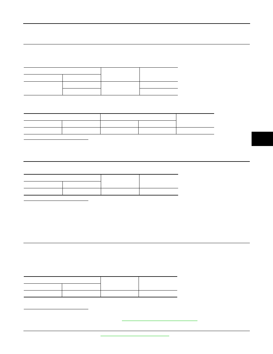
RAS motor relay
—
Continuity
Connector
Terminal
B36
2
Ground
Existed
1 Not
existed
RAS motor relay
RAS control unit
Continuity
Connector
Terminal
Connector
Terminal
B36
1
B37
25
Existed
RAS motor relay
—
Voltage (Approx.)
Connector
Terminal
B36
3
Ground
Battery voltage
RAS control unit
—
Voltage (Approx.)
Connector
Terminal
B37
25
Ground
Battery voltage
STC-54
< DTC/CIRCUIT DIAGNOSIS >
[WITH REAR ACTIVE STEER]
C1911, C1912 RAS MOTOR POWER SUPPLY
Is the inspection result normal?
YES
>> GO TO 6.
NO
>> Replace RAS motor relay.
6.
CHECK RAS MOTOR POWER SUPPLY
1.
Install RAS rear motor relay.
2.
Turn the ignition switch ON.
CAUTION:
Never start the engine.
3.
Check the voltage between RAS control unit harness connector and ground.
Is the inspection result normal?
YES
>> GO TO 7.
NO
>> Replace RAS control unit. Refer to
STC-109, "Removal and Installation"
.
7.
PERFORM SELF-DIAGNOSIS (RAS CONTROL UNIT)
With CONSULT-III
1.
Turn the ignition switch from OFF to ON.
2.
Perform “4WAS(MAIN)/RAS/HICAS” self-diagnosis.
Without CONSULT-III
1.
Start the engine.
2.
Perform the self-diagnosis. Refer to
STC-38, "Diagnosis Description"
.
Is DTC “C1911”, “C1912” or “RAS warning lamp flickering pattern:12” detected?
YES
>> Proceed to diagnosis procedure. Refer to
NO
>> GO TO 8.
8.
CHECK INFORMATION
With CONSULT-III
1.
Select “DATA MONITOR” of “4WAS(MAIN)/RAS/HICAS”.
2.
Check the “DATA MONITOR” value of each DTC detected with the self-diagnosis function. Refer to
.
Is each data the standard value?
YES
>> Check each harness connector pin terminal for disconnection.
NO
>> Replace RAS control unit. Refer to
STC-109, "Removal and Installation"
.
Component Inspection
INFOID:0000000005549681
1.
CHECK RAS MOTOR RELAY
1.
Turn the ignition switch OFF.
2.
Disconnect RAS motor relay harness connector.
3.
Apply 12 V to RAS motor relay connector No. 1 terminal and No. 2 terminal.
CAUTION:
• Never make the terminals short.
• Connect the fuse between the terminals when applying the voltage.
4.
Check the continuity between RAS motor relay connector.
5.
Check the resistance between RAS motor relay connector.
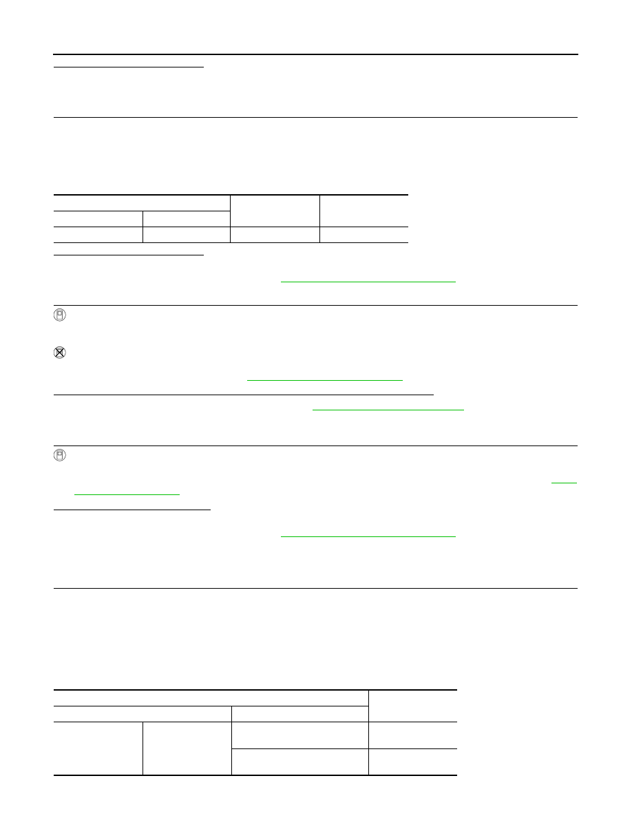
RAS control unit
—
Voltage (Approx.)
Connector
Terminal
B37
37
Ground
Battery voltage
RAS motor relay
Continuity
Terminal
Condition
3
5
Apply the voltage between No. 1
terminal and No. 2 terminal.
Existed
Do not apply the voltage between
No. 1 terminal and No. 2 terminal.
Not existed

C1911, C1912 RAS MOTOR POWER SUPPLY
STC-55
< DTC/CIRCUIT DIAGNOSIS >
[WITH REAR ACTIVE STEER]
C
D
E
F
H
I
J
K
L
M
A
B
STC
N
O
P
Is the inspection result normal?
YES
>> INSPECTION END
NO
>> Replace RAS motor relay.
Special Repair Requirement
INFOID:0000000005549683
BEFORE REPLACING RAS CONTROL UNIT
• Record the self-diagnosis results (history).
CAUTION:
• Never erase the memory (history) of self-diagnosis results when replacing RAS control unit after
diagnosis.
• Erase the memory of the self-diagnosis results (record) after printing out or recording all the val-
ues of “DATA MONITOR”.
RAS motor relay
Resistance (Approx.)
Terminal
1
2
50
Ω
STC-56
< DTC/CIRCUIT DIAGNOSIS >
[WITH REAR ACTIVE STEER]
C1914 REAR WHEEL STEERING ANGLE SENSOR
C1914 REAR WHEEL STEERING ANGLE SENSOR
Description
INFOID:0000000005549684
• It detects the steering angle condition of rear wheel.
• 2 systems (main and sub sensor) are equipped.
DTC Logic
INFOID:0000000005549685
DTC DETECTION LOGIC
DTC CONFIRMATION PROCEDURE
1.
DTC REPRODUCTION PROCEDURE
With CONSULT-III
1.
Turn the ignition switch from OFF to ON.
2.
Perform “4WAS(MAIN)/RAS/HICAS” self-diagnosis.
Without CONSULT-III
1.
Start the engine.
2.
Perform the self-diagnosis. Refer to
STC-38, "Diagnosis Description"
.
Is DTC “C1914” or “RAS warning lamp flickering pattern:24” detected?
YES
>> Proceed to diagnosis procedure. Refer to
NO
>> INSPECTION END
Diagnosis Procedure
INFOID:0000000005549686
1.
CHECK REAR WHEEL STEERING ANGLE SENSOR POWER SUPPLY
1.
Turn the ignition switch OFF.
2.
Check the voltage between RAS control unit harness connector and ground.
3.
Turn the ignition switch ON.
CAUTION:
Never start the engine.
4.
Check the voltage between RAS control unit harness connector and ground.
Is the inspection result normal?
YES
>> GO TO 2.
NO
>> Replace RAS control unit. Refer to
STC-109, "Removal and Installation"
.
2.
CHECK REAR WHEEL STEERING ANGLE SENSOR
Check the rear wheel steering angle sensor. Refer to
STC-57, "Component Inspection"
.
Is the inspection result normal?
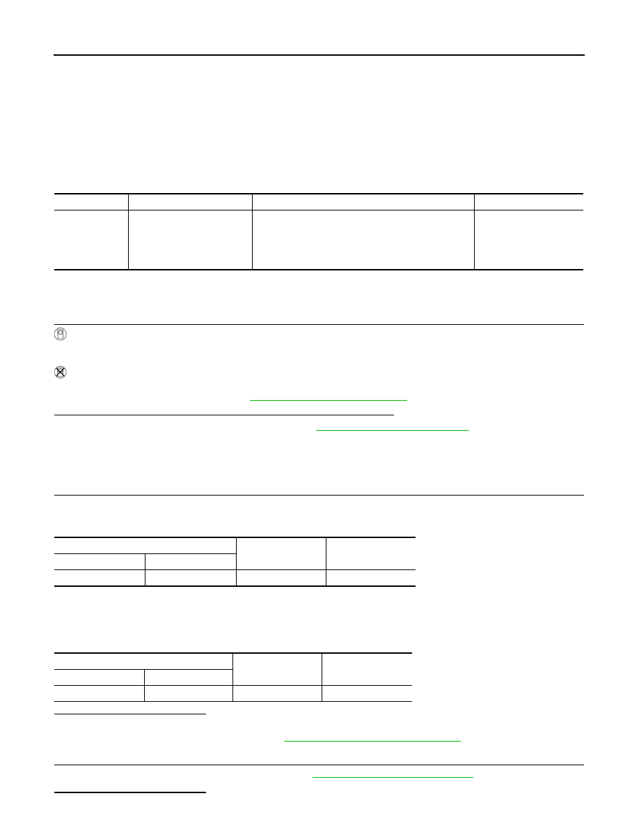
DTC
Display items
Malfunction detected condition
Possible cause
C1914
RR ST ANGLE SENSOR
[ABNORML VOL]
The rear wheel angle sensor (main) or (sub) power
supply value is malfunction.
• RAS actuator assembly
(Rear wheel angle sen-
sor)
• Harness or connector
• RAS control unit
RAS control unit
—
Voltage (Approx.)
Connector
Terminal
B37
5
Ground
0 V
RAS control unit
—
Value (Approx.)
Connector
Terminal
B37
5
Ground
5 V
Нет комментариевНе стесняйтесь поделиться с нами вашим ценным мнением.
Текст