Infiniti FX35, FX50 (S51). Manual — part 642
INTAKE VALVE TIMING CONTROL
EC-109
< SYSTEM DESCRIPTION >
[VQ35HR]
C
D
E
F
G
H
I
J
K
L
M
A
EC
N
P
O
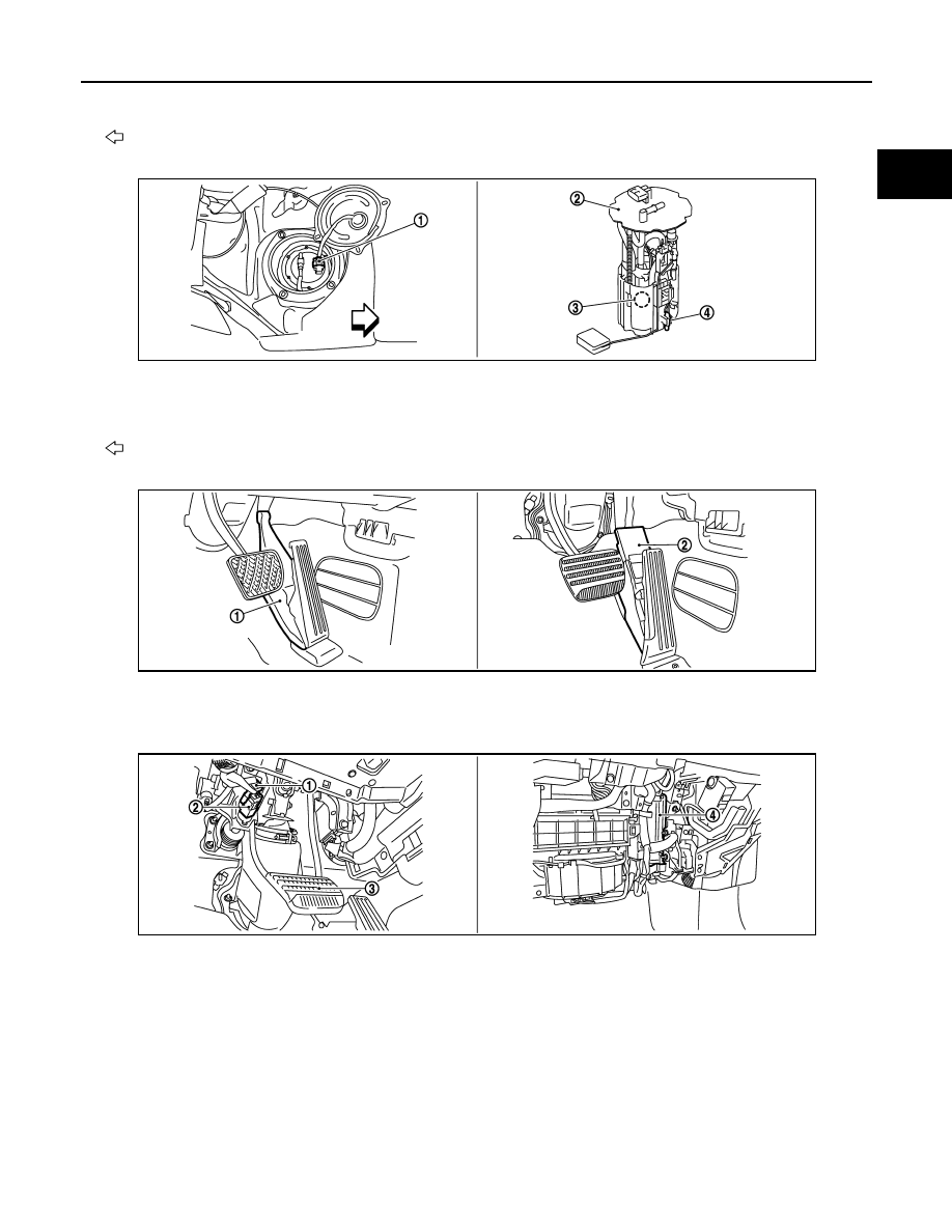
4.
EVAP canister
5.
EVAP control system pressure sen-
sor
: Vehicle front
1.
Fuel level sensor unit and fuel pump
harness connector
2.
Fuel level sensor unit and fuel pump 3.
Fuel pressure regulator
4.
Fuel tank temperature sensor
: Vehicle front
1.
Accelerator pedal position sensor
(Without DCA system)
2.
Accelerator pedal position sensor
(With DCA system)
1.
Stop lamp switch
2.
ASCD brake switch (ASCD models)
ICC brake switch (ICC models)
3.
Brake pedal
4.
ECM
JMBIA1504ZZ
JMBIA1505ZZ
JMBIA1509ZZ
EC-110
< SYSTEM DESCRIPTION >
[VQ35HR]
INTAKE VALVE TIMING CONTROL
Component Description
INFOID:0000000005236730
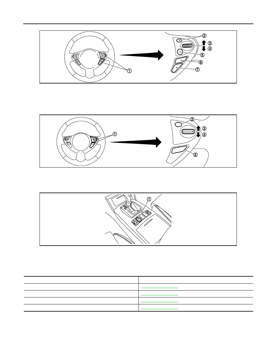
1.
ICC steering switch
2.
CANCEL switch
3.
RESUME/ACCELERATE switch
4.
SET/COAST switch
5.
DISTANCE switch
6.
MAIN switch
7.
LDP/DCA switch
1.
ASCD steering switch
2.
CANCEL switch
3.
RESUME/ACCELERATE switch
4.
SET/COAST switch
5.
MAIN switch
1.
Snow mode switch
JSBIA0155ZZ
JSBIA0156ZZ
JMBIA1623ZZ
Component
Reference
Camshaft position sensor
Crankshaft position sensor
Engine coolant temperature sensor
Intake valve timing control solenoid valve
ON BOARD DIAGNOSTIC (OBD) SYSTEM
EC-111
< SYSTEM DESCRIPTION >
[VQ35HR]
C
D
E
F
G
H
I
J
K
L
M
A
EC
N
P
O
ON BOARD DIAGNOSTIC (OBD) SYSTEM
Diagnosis Description
INFOID:0000000005236731
INTRODUCTION
The ECM has an on board diagnostic system, which detects malfunctions related to engine sensors or actua-
tors. The ECM also records various emission-related diagnostic information including:
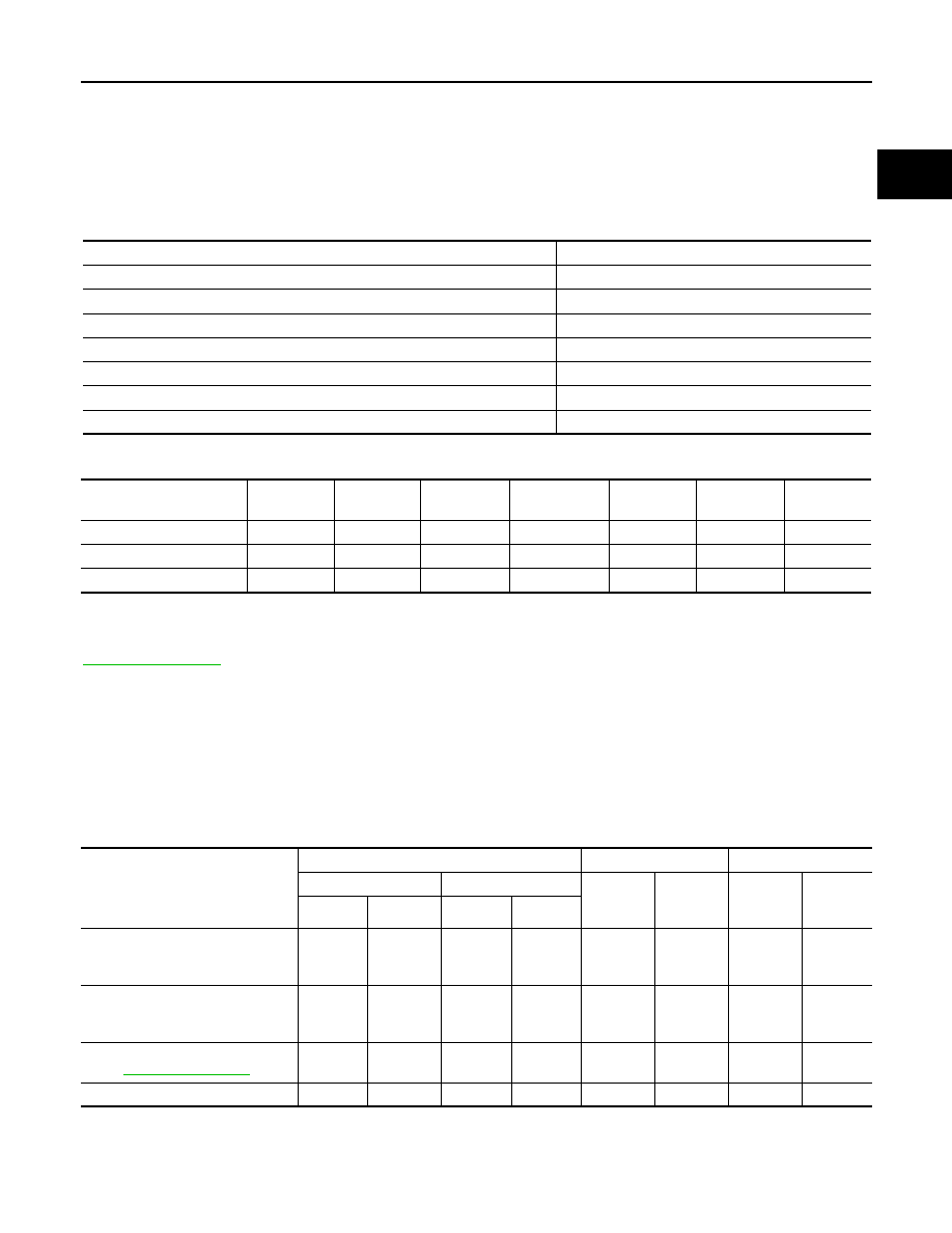
The above information can be checked using procedures listed in the table below.
×
: Applicable
—: Not applicable
*: When DTC and 1st trip DTC simultaneously appear on the display, they cannot be clearly distinguished from each other.
The malfunction indicator lamp (MIL) on the instrument panel illuminates when the same malfunction is
detected in two consecutive trips (Two trip detection logic), or when the ECM enters fail-safe mode. (Refer to
.)
TWO TRIP DETECTION LOGIC
When a malfunction is detected for the first time, 1st trip DTC and 1st trip Freeze Frame data are stored in the
ECM memory. The MIL will not illuminate at this stage. <1st trip>
If the same malfunction is detected again during the next drive, the DTC and Freeze Frame data are stored in
the ECM memory, and the MIL illuminates. The MIL illuminates at the same time when the DTC is stored.
<2nd trip> The “trip” in the “Two Trip Detection Logic” means a driving mode in which self-diagnosis is per-
formed during vehicle operation. Specific on board diagnostic items will cause the ECM to illuminate or blink
the MIL, and store DTC and Freeze Frame data, even in the 1st trip, as shown below.
×
: Applicable
—: Not applicable
DTC AND FREEZE FRAME DATA
DTC and 1st Trip DTC
Emission-related diagnostic information
Diagnostic service
Diagnostic Trouble Code (DTC)
Service $03 of SAE J1979/ISO 15031-5
Freeze Frame data
Service $02 of SAE J1979/ISO 15031-5
System Readiness Test (SRT) code
Service $01 of SAE J1979/ISO 15031-5
1st Trip Diagnostic Trouble Code (1st Trip DTC)
Service $07 of SAE J1979/ISO 15031-5
1st Trip Freeze Frame data
—
Test values and Test limits
Service $06 of SAE J1979/ISO 15031-5
Calibration ID
Service $09 of SAE J1979/ISO 15031-5
DTC
1st trip DTC
Freeze
Frame data
1st trip Freeze
Frame data
SRT code
SRT status
Test value
CONSULT-III
×
×
×
×
×
×
—
GST
×
×
×
—
×
×
×
ECM
×
×
*
—
—
—
×
—
Items
MIL
DTC
1st trip DTC
1st trip
2nd trip
1st trip
displaying
2nd trip
displaying
1st trip
displaying
2nd trip
display-
ing
Blinking
Illuminate
Blinking
Illuminate
Misfire (Possible three way catalyst
damage) — DTC: P0300 - P0306 is
being detected
×
—
—
—
—
—
×
—
Misfire (Possible three way catalyst
damage) — DTC: P0300 - P0306 is
being detected
—
—
×
—
—
×
—
—
One trip detection diagnoses (Re-
fer to
.)
—
×
—
—
×
—
—
—
Except above
—
—
—
×
—
×
×
—

EC-112
< SYSTEM DESCRIPTION >
[VQ35HR]
ON BOARD DIAGNOSTIC (OBD) SYSTEM
The 1st trip DTC (whose number is the same as the DTC number) is displayed for the latest self-diagnostic
result obtained. If the ECM memory was cleared previously, and the 1st trip DTC did not recur, the 1st trip DTC
will not be displayed.
If a malfunction is detected during the 1st trip, the 1st trip DTC is saved in the ECM memory. The MIL will not
illuminate (two trip detection logic). If the same malfunction is not detected in the 2nd trip (meeting the required
driving pattern), the 1st trip DTC is cleared from the ECM memory. If the same malfunction is detected in the
2nd trip, both the 1st trip DTC and DTC are stored in the ECM memory and the MIL illuminates. In other
words, the DTC is stored in the ECM memory and the MIL lights up when the same malfunction occurs in two
consecutive trips. If a 1st trip DTC is saved and a non-diagnostic operation is performed between the 1st and
2nd trips, only the 1st trip DTC will continue to be stored. For malfunctions that blink or illuminate the MIL dur-
ing the 1st trip, the DTC and 1st trip DTC are stored in the ECM memory.
Procedures for clearing the DTC and the 1st trip DTC from the ECM memory are described in “How to Erase
DTC and 1st trip DTC”.
For malfunctions in which 1st trip DTCs are displayed, refer to
. These items are
required by legal regulations to continuously monitor the system/component. In addition, the items monitored
non-continuously are also displayed on CONSULT-III.
1st trip DTC is specified in Service $07 of SAE J1979/ISO 15031-5. 1st trip DTC detection occurs without illu-
minating the MIL and therefore does not warn the driver of a malfunction. However, 1st trip DTC detection will
not prevent the vehicle from being tested, for example during Inspection/Maintenance (I/M) tests.
When a 1st trip DTC is detected, check, print out or write down and erase (1st trip) DTC and Freeze Frame
data as specified in Work Flow procedure Step 2, refer to
. Then perform DTC Confirma-
tion Procedure or Component Function Check to try to duplicate the malfunction. If the malfunction is dupli-
cated, the item requires repair.
Freeze Frame Data and 1st Trip Freeze Frame Data
The ECM records the driving conditions such as fuel system status, calculated load value, engine coolant tem-
perature, short-term fuel trim, long-term fuel trim, engine speed, vehicle speed, absolute throttle position, base
fuel schedule and intake air temperature at the moment a malfunction is detected.
Data which are stored in the ECM memory, along with the 1st trip DTC, are called 1st trip freeze frame data.
The data, stored together with the DTC data, are called freeze frame data and displayed on CONSULT-III or
GST. The 1st trip freeze frame data can only be displayed on the CONSULT-III screen, not on the GST.
Only one set of freeze frame data (either 1st trip freeze frame data or freeze frame data) can be stored in the
ECM. 1st trip freeze frame data is stored in the ECM memory along with the 1st trip DTC. There is no priority
for 1st trip freeze frame data and it is updated each time a different 1st trip DTC is detected. However, once
freeze frame data (2nd trip detection/MIL on) is stored in the ECM memory, 1st trip freeze frame data is no
longer stored. Remember, only one set of freeze frame data can be stored in the ECM. The ECM has the fol-
lowing priorities to update the data.
For example, the EGR malfunction (Priority: 2) was detected and the freeze frame data was saved in the 2nd
trip. After that when the misfire (Priority: 1) is detected in another trip, the freeze frame data will be updated
from the EGR malfunction to the misfire. The 1st trip freeze frame data is updated each time a different mal-
function is detected. There is no priority for 1st trip freeze frame data. However, once freeze frame data is
stored in the ECM memory, 1st trip freeze data is no longer stored (because only one freeze frame data or 1st
trip freeze frame data can be stored in the ECM). If freeze frame data is stored in the ECM memory and freeze
frame data with the same priority occurs later, the first (original) freeze frame data remains unchanged in the
ECM memory.
Both 1st trip freeze frame data and freeze frame data (along with the DTCs) are cleared when the ECM mem-
ory is erased. Procedures for clearing the ECM memory are described in “How to Erase DTC and 1st trip
DTC”.
How to Read DTC and 1st Trip DTC
With CONSULT-III
With GST
CONSULT-III or GST (Generic Scan Tool) Examples: P0340, P0850, P1148, etc.
These DTCs are prescribed by SAE J2012/ISO 15031-6.
Priority
Items
1
Freeze frame data
Misfire — DTC: P0300 - P0306
Fuel Injection System Function — DTC: P0171, P0172, P0174, P0175
2
Except the above items (Includes A/T related items)
3
1st trip freeze frame data
Нет комментариевНе стесняйтесь поделиться с нами вашим ценным мнением.
Текст