Infiniti FX35, FX50 (S51). Manual — part 1286

LAN-86
< DTC/CIRCUIT DIAGNOSIS >
[CAN]
LANE BRANCH LINE CIRCUIT
LANE BRANCH LINE CIRCUIT
Diagnosis Procedure
INFOID:0000000005241925
1.
CHECK CONNECTOR
1.
Turn the ignition switch OFF.
2.
Disconnect the battery cable from the negative terminal.
3.
Check the following terminals and connectors for damage, bend and loose connection (unit side and con-
nector side).
-
Lane camera unit
-
Harness connector R7
-
Harness connector M110
-
CAN gateway
Is the inspection result normal?
YES
>> GO TO 2.
NO
>> Repair the terminal and connector.
2.
CHECK HARNESS CONTINUITY (OPEN CIRCUIT)
1.
Disconnect the connector of CAN gateway.
2.
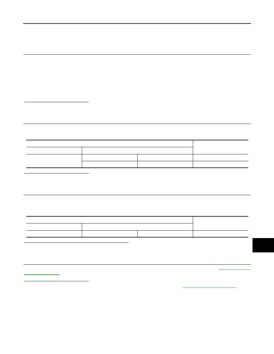
Check the continuity between the CAN gateway harness connector terminals.
Is the inspection result normal?
YES
>> GO TO 3.
NO
>> Check the harness and repair the root cause (CAN communication circuit 2).
3.
CHECK HARNESS FOR OPEN CIRCUIT
1.
Connect the connector of CAN gateway.
2.
Disconnect the connector of lane camera unit.
3.
Check the resistance between the lane camera unit harness connector terminals.
Is the measurement value within the specification?
YES
>> GO TO 4.
NO
>> Repair the lane camera unit branch line.
4.
CHECK POWER SUPPLY AND GROUND CIRCUIT
Check the power supply and the ground circuit of the lane camera unit. Refer to
.
Is the inspection result normal?
YES (Present error)>>Replace the lane camera unit. Refer to
.
YES (Past error)>>Error was detected in the lane camera unit branch line.
NO
>> Repair the power supply and the ground circuit.
CAN gateway harness connector
Continuity
Connector No.
Terminal No.
M125
6
4
Existed
12
10
Existed
Lane camera unit harness connector
Resistance (
Ω
)
Connector No.
Terminal No.
R8
10
5
Approx. 54 – 66
LAN
PSB BRANCH LINE CIRCUIT
LAN-87
< DTC/CIRCUIT DIAGNOSIS >
[CAN]
C
D
E
F
G
H
I
J
K
L
B
A
O
P
N
PSB BRANCH LINE CIRCUIT
Diagnosis Procedure
INFOID:0000000005241926
1.
CHECK CONNECTOR
1.
Turn the ignition switch OFF.
2.
Disconnect the battery cable from the negative terminal.
3.
Check the following terminals and connectors for damage, bend and loose connection (unit side and con-
nector side).
-
Pre-crash seat belt control unit
-
Harness connector B1
-
Harness connector M7
-
CAN gateway
Is the inspection result normal?
YES
>> GO TO 2.
NO
>> Repair the terminal and connector.
2.
CHECK HARNESS CONTINUITY (OPEN CIRCUIT)
1.
Disconnect the connector of CAN gateway.
2.
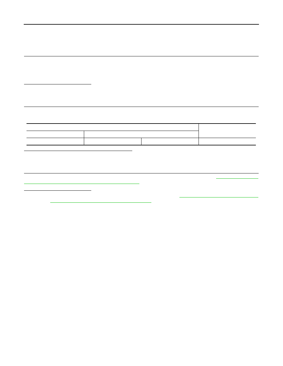
Check the continuity between the CAN gateway harness connector terminals.
Is the inspection result normal?
YES
>> GO TO 3.
NO
>> Check the harness and repair the root cause (CAN communication circuit 2).
3.
CHECK HARNESS FOR OPEN CIRCUIT
1.
Connect the connector of CAN gateway.
2.
Disconnect the connector of pre-crash seat belt control unit.
3.
Check the resistance between the pre-crash seat belt control unit harness connector terminals.
Is the measurement value within the specification?
YES
>> GO TO 4.
NO
>> Repair the pre-crash seat belt control unit branch line.
4.
CHECK POWER SUPPLY AND GROUND CIRCUIT
Check the power supply and the ground circuit of the pre-crash seat belt control unit. Refer to
.
Is the inspection result normal?
YES (Present error)>>Replace the pre-crash seat belt control unit. Refer to
YES (Past error)>>Error was detected in the pre-crash seat belt control unit branch line.
NO
>> Repair the power supply and the ground circuit.
CAN gateway harness connector
Continuity
Connector No.
Terminal No.
M125
6
4
Existed
12
10
Existed
Pre-crash seat belt control unit harness connector
Resistance (
Ω
)
Connector No.
Terminal No.
B9
14
4
Approx. 54 – 66
LAN-88
< DTC/CIRCUIT DIAGNOSIS >
[CAN]
APA BRANCH LINE CIRCUIT
APA BRANCH LINE CIRCUIT
Diagnosis Procedure
INFOID:0000000005241927
1.
CHECK CONNECTOR
1.
Turn the ignition switch OFF.
2.
Disconnect the battery cable from the negative terminal.
3.
Check the terminals and connectors of the accelerator pedal actuator for damage, bend and loose con-
nection (unit side and connector side).
Is the inspection result normal?
YES
>> GO TO 2.
NO
>> Repair the terminal and connector.
2.
CHECK HARNESS FOR OPEN CIRCUIT
1.
Disconnect the connector of accelerator pedal actuator.
2.
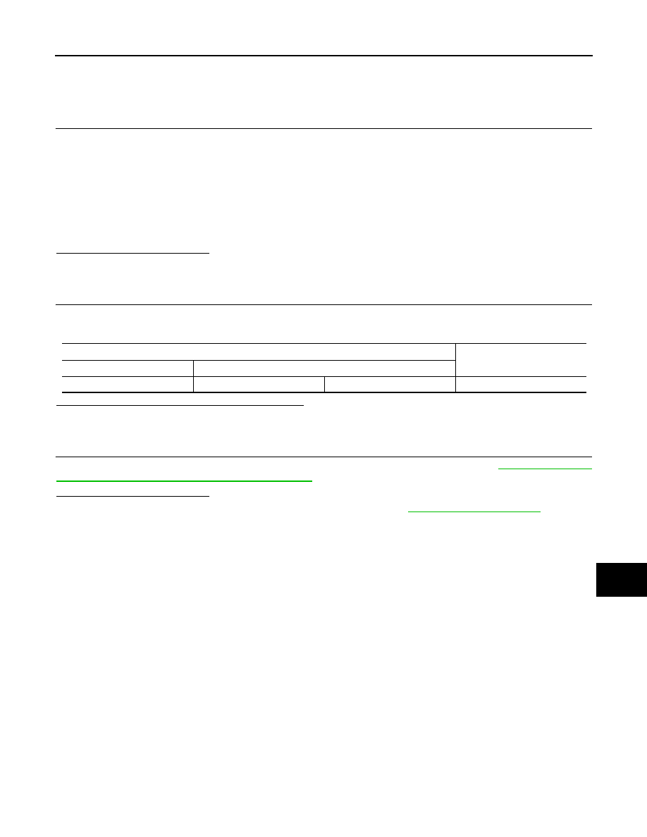
Check the resistance between the accelerator pedal actuator harness connector terminals.
Is the measurement value within the specification?
YES
>> GO TO 3.
NO
>> Repair the accelerator pedal actuator branch line.
3.
CHECK POWER SUPPLY AND GROUND CIRCUIT
Check the power supply and the ground circuit of the accelerator pedal actuator. Refer to
ERATOR PEDAL ACTUATOR : Diagnosis Procedure"
Is the inspection result normal?
YES (Present error)>>Replace the accelerator pedal actuator. Refer to
CONTROL ASSIST SYSTEM : Exploded View"
.
YES (Past error)>>Error was detected in the accelerator pedal actuator branch line.
NO
>> Repair the power supply and the ground circuit.
Accelerator pedal actuator harness connector
Resistance (
Ω
)
Connector No.
Terminal No.
E115
5
3
Approx. 54 – 66
LAN
BCU BRANCH LINE CIRCUIT
LAN-89
< DTC/CIRCUIT DIAGNOSIS >
[CAN]
C
D
E
F
G
H
I
J
K
L
B
A
O
P
N
BCU BRANCH LINE CIRCUIT
Diagnosis Procedure
INFOID:0000000005241928
1.
CHECK CONNECTOR
1.
Turn the ignition switch OFF.
2.
Disconnect the battery cable from the negative terminal.
3.
Check the following terminals and connectors for damage, bend and loose connection (unit side and con-
nector side).
-
Brake booster control unit
-
Harness connector B201
-
Harness connector M117
-
Harness connector M6
-
Harness connector E106
Is the inspection result normal?
YES
>> GO TO 2.
NO
>> Repair the terminal and connector.
2.
CHECK HARNESS FOR OPEN CIRCUIT
1.
Disconnect the connector of brake booster control unit.
2.
Check the resistance between the brake booster control unit harness connector terminals.
Is the measurement value within the specification?
YES
>> GO TO 3.
NO
>> Repair or replace (if shield line is open) the brake booster control unit branch line.
3.
CHECK POWER SUPPLY AND GROUND CIRCUIT
Check the power supply and the ground circuit of the brake booster control unit. Refer to
BOOSTER CONTROL UNIT : Diagnosis Procedure"
.
Is the inspection result normal?
YES (Present error)>>Replace the brake booster control unit. Refer to
.
YES (Past error)>>Error was detected in the brake booster control unit branch line.
NO
>> Repair the power supply and the ground circuit.
Brake booster control unit harness connector
Resistance (
Ω
)
Connector No.
Terminal No.
B250
14
5
Approx. 108 – 132
Нет комментариевНе стесняйтесь поделиться с нами вашим ценным мнением.
Текст