Infiniti FX35, FX50 (S51). Manual — part 130

AV
POWER SUPPLY AND GROUND CIRCUIT
AV-293
< DTC/CIRCUIT DIAGNOSIS >
[NAVIGATION (SINGLE MONITOR)]
C
D
E
F
G
H
I
J
K
L
M
B
A
O
P
AROUND VIEW MONITOR CONTROL UNIT : Diagnosis Procedure
INFOID:0000000005475816
1.
CHECK FUSE
Check for blown fuses.
Is inspection result normal?
YES
>> GO TO 2.
NO
>> Be sure to eliminate cause of malfunction before installing new fuse.
2.
CHECK POWER SUPPLY CIRCUITS
Check voltage between around view monitor control unit harness connector and ground.
Is inspection result normal?
YES
>> GO TO 3.
NO
>> Check harness between around view monitor control unit and fuse.
3.
CHECK GROUND CIRCUIT
1.
Turn ignition switch OFF.
2.
Disconnect around view monitor control unit connector.
3.
Check continuity between around view monitor control unit harness connector and ground.
Is inspection result normal?
YES
>> INSPECTION END
NO
>> Repair harness or connector.
SONAR CONTROL UNIT (WITH AROUND VIEW MONITOR)
SONAR CONTROL UNIT (WITH AROUND VIEW MONITOR) : Diagnosis Procedure
INFOID:0000000005475817
1.
CHECK FUSE
Check for blown fuses.
Is the inspection result normal?
YES
>> GO TO 2.
NO
>> Be sure to eliminate cause of malfunction before installing new fuse.
2.
CHECK POWER SUPPLY CIRCUIT
1.
Turn ignition switch ON.
2.
Check voltage between sonar control unit harness connector and ground.
Is the inspection result normal?
Power source
Fuse No.
Battery
34
Ignition switch ACC
19
Signal name
Connector No.
Terminal No.
Ignition switch position
Value (Approx.)
Battery power supply
B46
2
OFF
Battery voltage
ACC power supply
B46
4
ACC
Battery voltage
Signal name
Connector No.
Terminal No.
Ignition switch position
Continuity
Ground
B46
1
OFF
Existed
Power source
Fuse No.
Ignition switch ACC or ON
19
Signal name
Connector No.
Terminal No.
Ignition switch position
Value (Approx.)
Battery power supply
M47
13
ACC
Battery voltage

AV-294
< DTC/CIRCUIT DIAGNOSIS >
[NAVIGATION (SINGLE MONITOR)]
POWER SUPPLY AND GROUND CIRCUIT
YES
>> GO TO 3.
NO
>> Repair or replace sonar control unit power supply harness.
3.
CHECK GROUND CIRCUIT
1.
Turn ignition switch OFF.
2.
Disconnect sonar control unit connector.
3.
Check continuity between sonar control unit harness connector and ground.
Is the inspection result normal?
YES
>> INSPECTION END
NO
>> Repair or replace sonar control unit ground harness.
Signal name
Connector No.
Terminal No.
Ignition switch position
Continuity
Ground
M47
24
OFF
Existed
AV
RGB DIGITAL IMAGE SIGNAL CIRCUIT
AV-295
< DTC/CIRCUIT DIAGNOSIS >
[NAVIGATION (SINGLE MONITOR)]
C
D
E
F
G
H
I
J
K
L
M
B
A
O
P
RGB DIGITAL IMAGE SIGNAL CIRCUIT
Description
INFOID:0000000005475900
Transmit the image displayed with AV control unit with RGB digital image signal to the display unit.
Diagnosis Procedure
INFOID:0000000005475901
1.
CHECK CONTINUITY RGB DIGITAL IMAGE SIGNAL CIRCUIT
1.
Turn ignition switch OFF.
2.
Disconnect display unit connector and AV control unit connector.
3.
Check continuity between front display unit harness connector and AV control unit harness connector.
4.
Check continuity between front display unit harness connector and ground.
Is the inspection result normal?
YES
>> GO TO 2.
NO
>> Repair harness or connector.
2.
CHECK RGB DIGITAL IMAGE SIGNAL
1.
Connect AV control unit connector.
2.
Turn ignition switch ON.
3.
Check signal between front display unit harness connector and ground.
Is the inspection result normal?
YES
>> Replace front display unit. Refer to
.
NO
>> Replace AV control unit. Refer to
Front display unit
AV control unit
Continuity
Connector
Terminals
Connector
Terminals
M397
27
M396
157
Existed
28
158
Front display unit
Ground
Continuity
Connector
Terminals
M397
27
Not existed
28
(+)
(
−
)
Condition
Voltage
(Approx.)
Front display unit
Connector
Terminal
M397
27
Ground
—
3.0 V
28
AV-296
< DTC/CIRCUIT DIAGNOSIS >
[NAVIGATION (SINGLE MONITOR)]
COMPOSITE IMAGE SIGNAL CIRCUIT
COMPOSITE IMAGE SIGNAL CIRCUIT
Description
INFOID:0000000005475902
• DVD is played by inserting DVD into the AV control unit.
• DVD image signals are transmitted to the front display unit.
• AV control unit receives the image signal from the auxiliary input jacks and USB (video data) and then trans-
mits it to the front display unit.
Diagnosis Procedure
INFOID:0000000005475903
1.
CHECK CONTINUITY COMPOSITE IMAGE SIGNAL CIRCUIT
1.
Turn ignition switch OFF.
2.
Disconnect AV control unit connector and front display unit connector.
3.
Check continuity between AV control unit harness connector and front display unit harness connector.
4.
Check continuity between AV control unit harness connector and ground.
Is the inspection result normal?
YES
>> GO TO 2.
NO
>> Repair harness or connector.
2.
CHECK AUX COMPOSITE SIGNAL
1.
Connect AV control unit connector and front display unit connector.
2.
Turn ignition switch ON.
3.
Check signal between auxiliary input jacks harness connector and ground.
Is the inspection result normal?
YES
>> Replace front display unit. Refer to
.
NO
>> Replace AV control unit. Refer to
AV control unit
Front display unit
Continuity
Connector
Terminal
Connector
Terminal
M210
68
M195
18
Existed
AV control unit
Ground
Continuity
Connector
Terminal
M210
68
Not existed
(+)
(
−
)
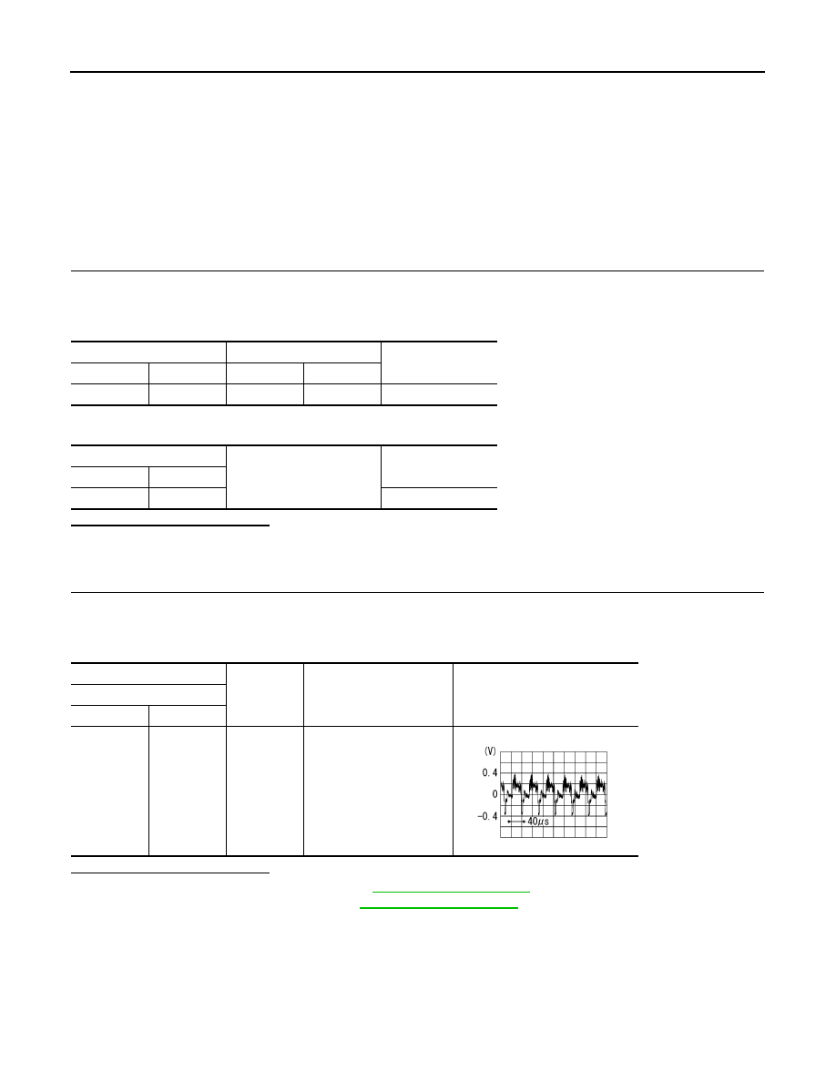
Condition
Reference value
AV control unit
Connector
Terminal
M210
68
Ground
At DVD image is displayed.
SKIB2251J
Нет комментариевНе стесняйтесь поделиться с нами вашим ценным мнением.
Текст