Infiniti FX35, FX50 (S51). Manual — part 965
EM-160
< PREPARATION >
[VK50VE]
PREPARATION
Commercial Service Tool
INFOID:0000000005245207
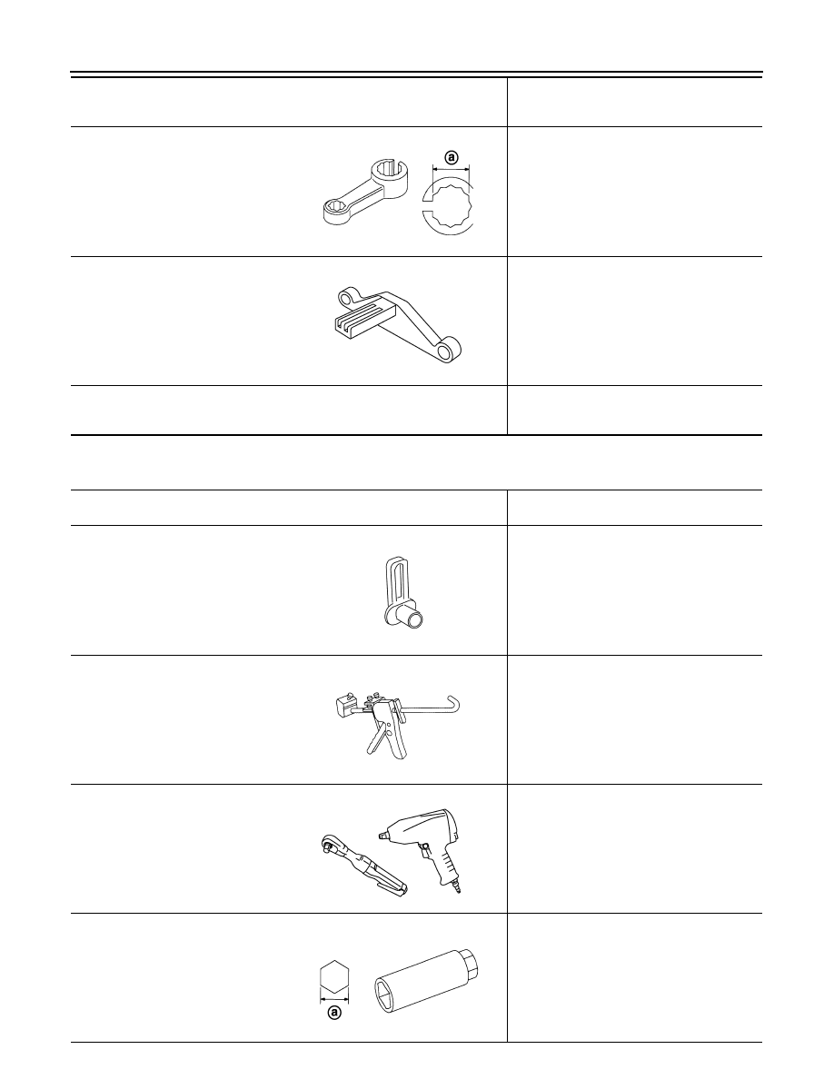
KV10114400
(J-38365)
Heated oxygen sensor wrench
Loosening or tightening air fuel ratio sensor 1
and heated oxygen sensor 2
a: 22 mm (0.87 in)
KV10119200
(J-49277)
Ring gear stopper
Removing and installing crankshaft pulley
KV10119300
(
—
)
Adapter and torque wrench assembly
Tightening rocker cover mounting bolts.
(specified torque)
Tool number
(Kent-Moore No.)
Tool name
Description
JPBIA0397ZZ
JPBIA0409ZZ
(Kent-Moore No.)
Tool name
Description
(J-45488)
Quick connector release
Removing fuel tube quick connectors in en-
gine room
(
—
)
Tube presser
Pressing the tube of liquid gasket
(
—
)
Power tool
Loosening nuts and bolts
(
—
)
Spark plug wrench
Removing and installing spark plug
a: 14 mm (0.55 in)
PBIC0198E
S-NT052
PBIC0190E
JPBIA0399ZZ
PREPARATION
EM-161
< PREPARATION >
[VK50VE]
C
D
E
F
G
H
I
J
K
L
M
A
EM
N
P
O
(
—
)
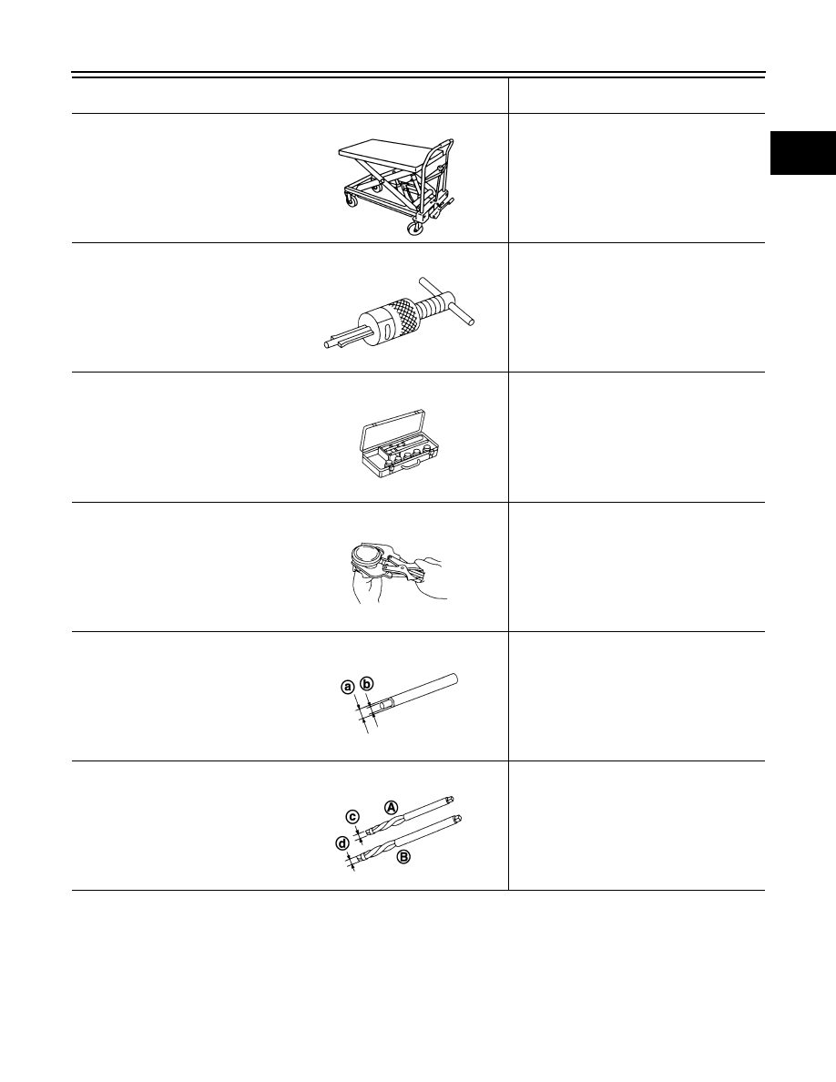
Manual lift table caddy
Removing and installing engine
(
—
)
Pilot bushing puller
Removing pilot converter
(
—
)
Valve seat cutter set
Finishing valve seat (EXH) dimensions
(
—
)
Piston ring expander
Removing and installing piston ring
(
—
)
Valve guide drift
Removing and installing valve guide (EXH)
a: 9.5 mm (0.374 in) dia.
b: 5.5 mm (0.217 in) dia.
(
—
)
Valve guide reamer
(1): Reaming valve guide (EXH) inner hole
(2): Reaming hole for oversize valve guide
(EXH)
c: 6.0 mm (0.236 in) dia.
d: 10.2 mm (0.402 in) dia.
(Kent-Moore No.)
Tool name
Description
ZZA1210D
NT045
S-NT048
S-NT030
JPBIA0400ZZ
JPBIA0401ZZ
EM-162
< PREPARATION >
[VK50VE]
PREPARATION
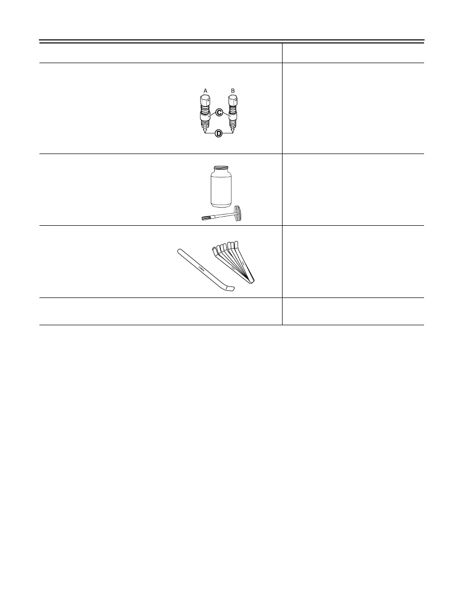
(J-43897-18)
(J-43897-12)
Oxygen sensor thread cleaner
Reconditioning the exhaust system threads
before installing a new air fuel ratio sensor and
heated oxygen sensor (Use with anti-seize lu-
bricant shown below.)
A: J-43897-18 [18 mm (0.71 in) dia.] for zir-
conia heated oxygen sensor and air fuel
ratio sensor
B: J-43897-12 [12 mm (0.47 in) dia.] for tita-
nia heated oxygen sensor
C: Mating surface shave cylinder
D: Flutes
(
—
)
Anti-seize lubricant (Permatex 133AR
or equivalent meeting MIL specifica-
tion MIL-A-907)
Lubricating oxygen sensor thread cleaning
tool when reconditioning exhaust system
threads
(
—
)
Feeler gauge
Inspection valve clearance (use a curved-tip
gauge)
(
—
)
Compression gauge with flexible type
adapter
Checking compression pressure
(Kent-Moore No.)
Tool name
Description
JPBIA0238ZZ
AEM489
JPBIA1362ZZ
DRIVE BELTS
EM-163
< PERIODIC MAINTENANCE >
[VK50VE]
C
D
E
F
G
H
I
J
K
L
M
A
EM
N
P
O
PERIODIC MAINTENANCE
DRIVE BELTS
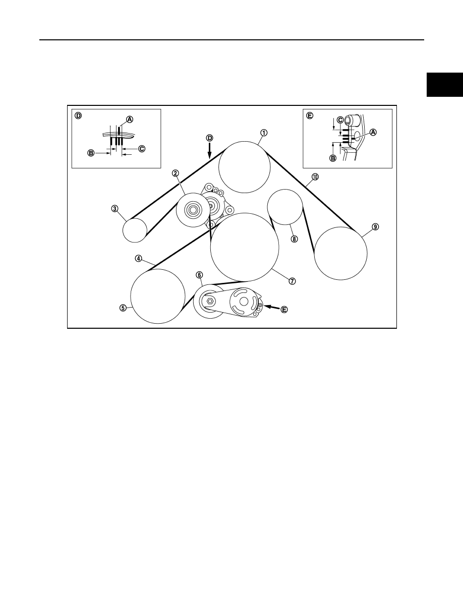
Exploded View
INFOID:0000000005245208
Checking
INFOID:0000000005245209
WARNING:
Be sure to perform the these steps when engine is stopped.
• Remove air duct (inlet) when inspecting alternator, water pump and A/C compressor belt.
• Remove engine undercover with power tool when inspecting power steering oil pump belt.
• Check that the indicator (A) (notch on fixed side) of each auto-tensioner is within the possible use range (B).
NOTE:
• Check the each auto-tensioners indication when the engine is cold.
• When new drive belts is installed, the indicator (notch on fixed side) should be within the range (C) in the
figure.
• Visually check all drive belts for wear, damage or cracks.
• If the indicator (notch on fixed side) is out of the possible use range or drive belts are damaged, replace drive
belts.
1.
Water pump
2.
Auto-tensioner (for alternator, water
pump and A/C compressor belt)
3.
Alternator
4.
Power steering oil pump belt
5.
Power steering oil pump
6.
Auto-tensioner (for power steering oil
pump belt)
7.
Crankshaft pulley
8.
Idler pulley
9.
A/C compressor
10.
Alternator, water pump and A/C com-
pressor belt
A.
Indicator
B.
Possible use range
C.
Range when new drive belt is installed
D.
View D
E.
View E
JPBIA2065ZZ
Нет комментариевНе стесняйтесь поделиться с нами вашим ценным мнением.
Текст