Infiniti FX35, FX50 (S51). Manual — part 1269

LAN-18
< SYSTEM DESCRIPTION >
[CAN FUNDAMENTAL]
TROUBLE DIAGNOSIS
With PAST
MONITOR ITEM (ON-BOARD DIAGNOSIS)
NOTE:
For some models, CAN communication diagnosis result is received from the vehicle monitor.
Example: Vehicle Display
Transmission diagnosis
OK
Normal at present
UNKWN
Unable to transmit signals for 2 seconds or more.
Diagnosis not performed
Control unit name
(Reception diagnosis)
OK
Normal at present
UNKWN
Unable to receive signals for 2 seconds or more.
Diagnosis not performed
No control unit for receiving signals. (No applicable optional parts)
Item
PRSNT
Description
Item
PRSNT
PAST
Description
Transmission diagnosis
OK
OK
Normal at present and in the past
1 – 39
Normal at present, but unable to transmit signals for 2 seconds or more
in the past. (The number indicates the number of ignition switch cycles
from OFF to ON.)
UNKWN
0
Unable to transmit signals for 2 seconds or more at present.
Control unit name
(Reception diagnosis)
OK
OK
Normal at present and in the past
1 – 39
Normal at present, but unable to receive signals for 2 seconds or more
in the past. (The number indicates the number of ignition switch cycles
from OFF to ON.)
UNKWN
0
Unable to receive signals for 2 seconds or more at present.
–
–
Diagnosis not performed.
No control unit for receiving signals. (No applicable optional parts)
Item
Result indi-
cated
Error counter
Description
CAN_COMM
(Initial diagnosis)
OK
0
Normal at present
NG
1 – 50
Control unit error
(The number indicates how many times diagnosis has been
run.)
CAN_CIRC_1
(Transmission diagnosis)
OK
0
Normal at present
UNKWN
1 – 50
Unable to transmit for 2 seconds or more at present.
(The number indicates how many times diagnosis has been
run.)
CAN_CIRC_2 – 9
(Reception diagnosis of each unit)
OK
0
Normal at present
UNKWN
1 – 50
Unable to transmit for 2 seconds or more at present.
(The number indicates how many times diagnosis has been
run.)
Diagnosis not performed.
No control unit for receiving signals. (No applicable optional
parts)
LAN
TROUBLE DIAGNOSIS
LAN-19
< SYSTEM DESCRIPTION >
[CAN FUNDAMENTAL]
C
D
E
F
G
H
I
J
K
L
B
A
O
P
N
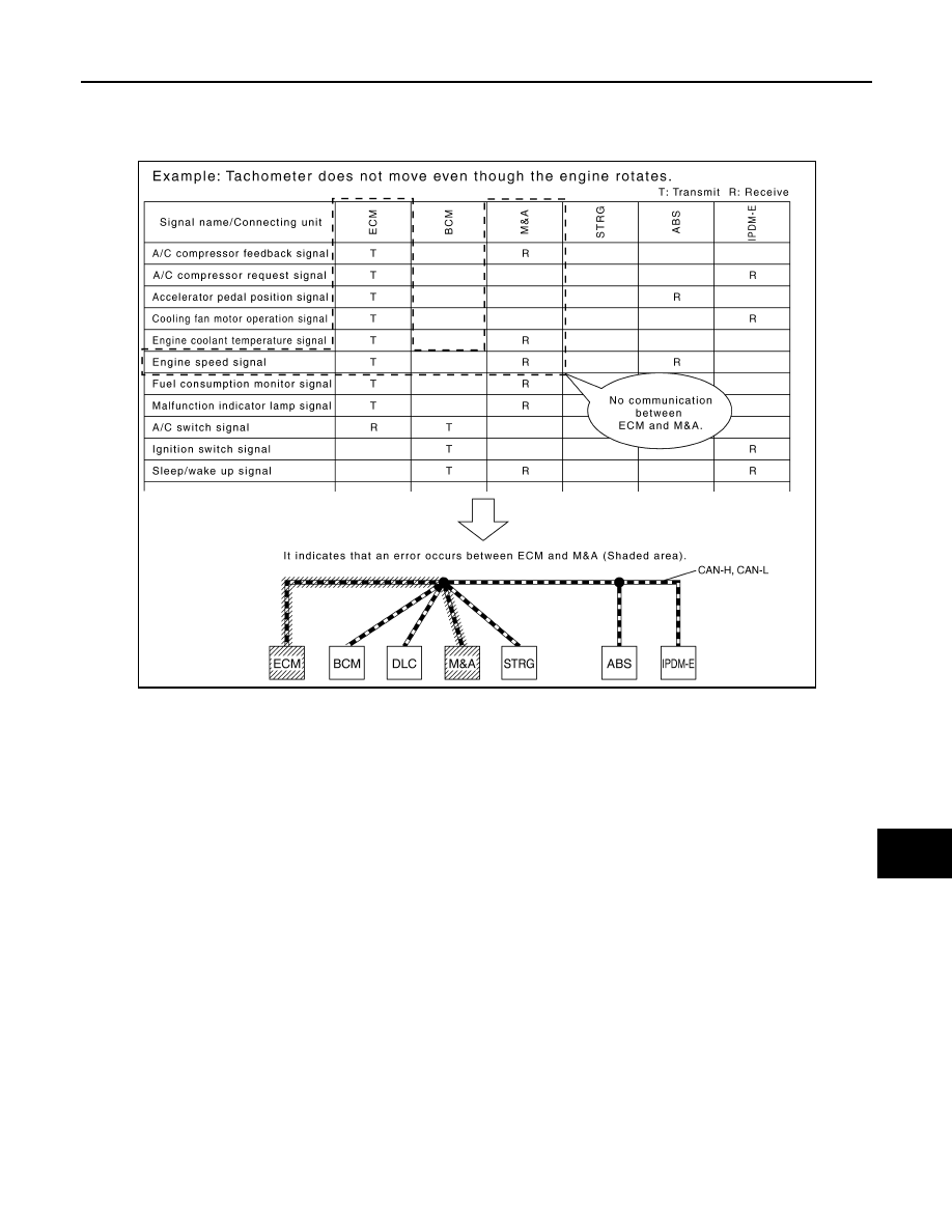
How to Use CAN Communication Signal Chart
INFOID:0000000005568437
The CAN communication signal chart lists the signals needed for trouble diagnosis. It is useful for detecting
the root cause by finding a signal related to the symptom, and by checking transmission and reception unit.
SKIB8715E
LAN-20
< BASIC INSPECTION >
[CAN FUNDAMENTAL]
DIAGNOSIS AND REPAIR WORKFLOW
BASIC INSPECTION
DIAGNOSIS AND REPAIR WORKFLOW
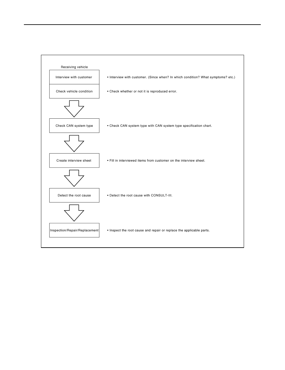
Trouble Diagnosis Flow Chart
INFOID:0000000005568438
Trouble Diagnosis Procedure
INFOID:0000000005568439
INTERVIEW WITH CUSTOMER
Interview with the customer is important to detect the root cause of CAN communication system errors and to
understand vehicle condition and symptoms for proper trouble diagnosis.
Points in interview
• What: Parts name, system name
• When: Date, Frequency
• Where: Road condition, Place
• In what condition: Driving condition/environment
• Result: Symptom
NOTE:
• Check normal units as well as error symptoms.
- Example: Circuit between ECM and the combination meter is judged normal if the customer indicates
tachometer functions normally.
• When a CAN communication system error is present, multiple control units may malfunction or go into fail-
safe mode.
JSMIA0016GB
LAN
DIAGNOSIS AND REPAIR WORKFLOW
LAN-21
< BASIC INSPECTION >
[CAN FUNDAMENTAL]
C
D
E
F
G
H
I
J
K
L
B
A
O
P
N
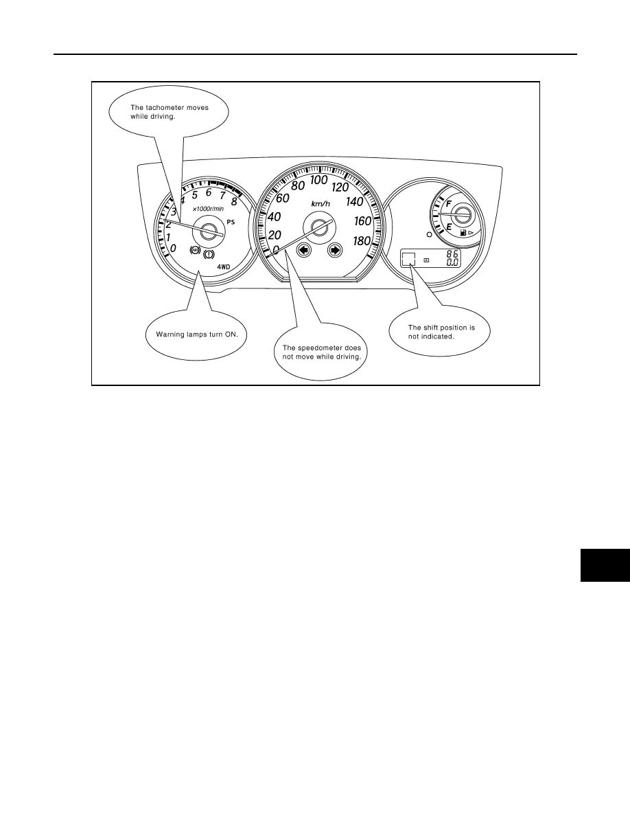
• Indication of the combination meter is important to detect the root cause because it is the most obvious to
the customer, and it performs CAN communication with many units.
INSPECTION OF VEHICLE CONDITION
Check whether the symptom is reproduced or not.
NOTE:
Do not turn the ignition switch OFF or disconnect the battery cable while reproducing the error. The error may
temporarily correct itself, making it difficult to determine the root cause.
CHECK OF CAN SYSTEM TYPE (HOW TO USE CAN SYSTEM TYPE SPECIFICATION CHART)
Determine CAN system type based on vehicle equipment.
NOTE:
• This chart is used if CONSULT-III does not automatically recognize CAN system type.
• There are two styles for CAN system type specification charts. Depending on the number of available sys-
tem types, either style A or style B may be used.
CAN System Type Specification Chart (Style A)
NOTE:
SKIB8717E
Нет комментариевНе стесняйтесь поделиться с нами вашим ценным мнением.
Текст