Infiniti FX35, FX50 (S51). Manual — part 1305

LAN-162
< DTC/CIRCUIT DIAGNOSIS >
[CAN SYSTEM (TYPE 3)]
ABS BRANCH LINE CIRCUIT
ABS BRANCH LINE CIRCUIT
Diagnosis Procedure
INFOID:0000000005576975
1.
CHECK CONNECTOR
1.
Turn the ignition switch OFF.
2.
Disconnect the battery cable from the negative terminal.
3.
Check the terminals and connectors of the ABS actuator and electric unit (control unit) for damage, bend
and loose connection (unit side and connector side).
Is the inspection result normal?
YES
>> GO TO 2.
NO
>> Repair the terminal and connector.
2.
CHECK HARNESS FOR OPEN CIRCUIT
1.
Disconnect the connector of ABS actuator and electric unit (control unit).
2.
Check the resistance between the ABS actuator and electric unit (control unit) harness connector termi-
nals.
Is the measurement value within the specification?
YES
>> GO TO 3.
NO
>> Repair the ABS actuator and electric unit (control unit) branch line.
3.
CHECK POWER SUPPLY AND GROUND CIRCUIT
Check the power supply and the ground circuit of the ABS actuator and electric unit (control unit). Refer to
Is the inspection result normal?
YES (Present error)>>Replace the ABS actuator and electric unit (control unit). Refer to
YES (Past error)>>Error was detected in the ABS actuator and electric unit (control unit) branch line.
NO
>> Repair the power supply and the ground circuit.
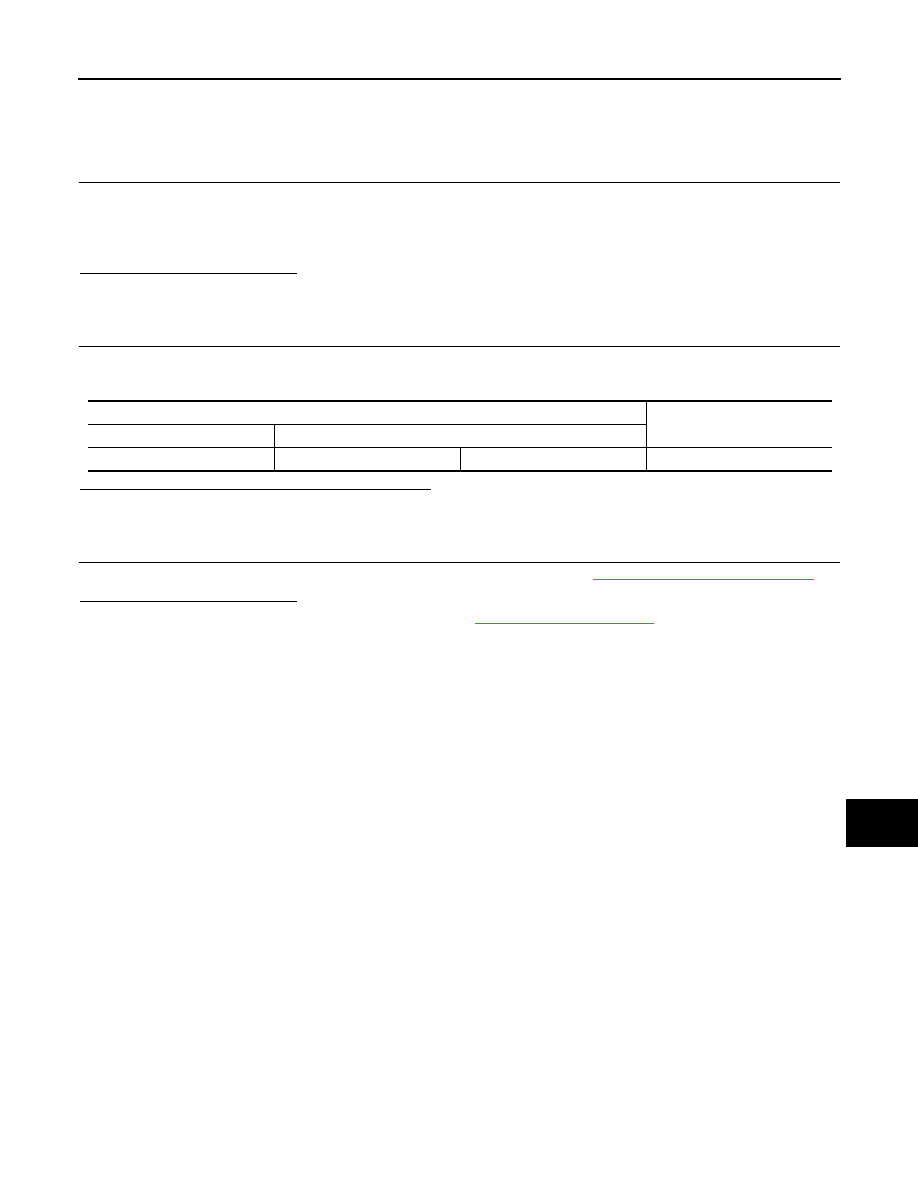
ABS actuator and electric unit (control unit) harness connector
Resistance (
Ω
)
Connector No.
Terminal No.
E41
35
14
Approx. 54 – 66
LAN
IPDM-E BRANCH LINE CIRCUIT
LAN-163
< DTC/CIRCUIT DIAGNOSIS >
[CAN SYSTEM (TYPE 3)]
C
D
E
F
G
H
I
J
K
L
B
A
O
P
N
IPDM-E BRANCH LINE CIRCUIT
Diagnosis Procedure
INFOID:0000000005576976
1.
CHECK CONNECTOR
1.
Turn the ignition switch OFF.
2.
Disconnect the battery cable from the negative terminal.
3.
Check the terminals and connectors of the IPDM E/R for damage, bend and loose connection (unit side
and connector side).
Is the inspection result normal?
YES
>> GO TO 2.
NO
>> Repair the terminal and connector.
2.
CHECK HARNESS FOR OPEN CIRCUIT
1.
Disconnect the connector of IPDM E/R.
2.
Check the resistance between the IPDM E/R harness connector terminals.
Is the measurement value within the specification?
YES
>> GO TO 3.
NO
>> Repair the IPDM E/R branch line.
3.
CHECK POWER SUPPLY AND GROUND CIRCUIT
Check the power supply and the ground circuit of the IPDM E/R. Refer to
Is the inspection result normal?
YES (Present error)>>Replace the IPDM E/R. Refer to
YES (Past error)>>Error was detected in the IPDM E/R branch line.
NO
>> Repair the power supply and the ground circuit.
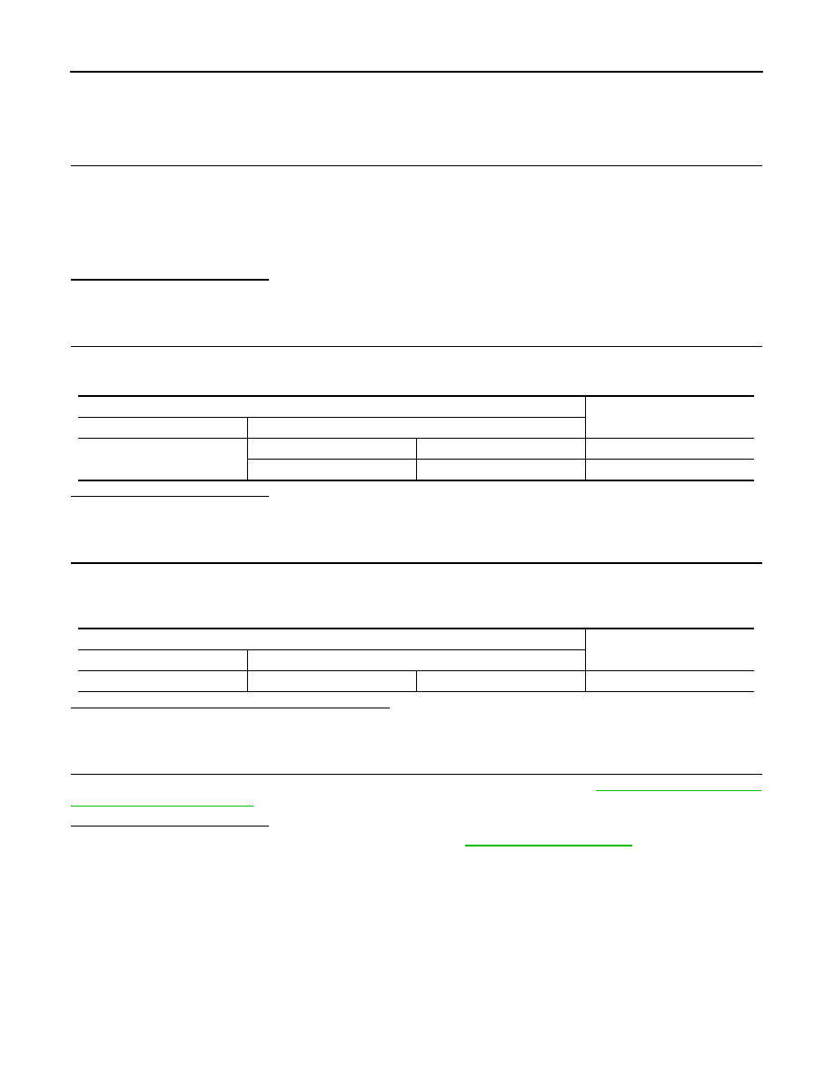
IPDM E/R harness connector
Resistance (
Ω
)
Connector No.
Terminal No.
E6
40
39
Approx. 108 – 132
LAN-164
< DTC/CIRCUIT DIAGNOSIS >
[CAN SYSTEM (TYPE 3)]
AFS BRANCH LINE CIRCUIT
AFS BRANCH LINE CIRCUIT
Diagnosis Procedure
INFOID:0000000005576977
1.
CHECK CONNECTOR
1.
Turn the ignition switch OFF.
2.
Disconnect the battery cable from the negative terminal.
3.
Check the following terminals and connectors for damage, bend and loose connection (unit side and con-
nector side).
-
AFS control unit
-
CAN gateway
Is the inspection result normal?
YES
>> GO TO 2.
NO
>> Repair the terminal and connector.
2.
CHECK HARNESS CONTINUITY (OPEN CIRCUIT)
1.
Disconnect the connector of CAN gateway.
2.
Check the continuity between the CAN gateway harness connector terminals.
Is the inspection result normal?
YES
>> GO TO 3.
NO
>> Check the harness and repair the root cause (CAN communication circuit 2).
3.
CHECK HARNESS FOR OPEN CIRCUIT
1.
Connect the connector of CAN gateway.
2.
Disconnect the connector of AFS control unit.
3.
Check the resistance between the AFS control unit harness connector terminals.
Is the measurement value within the specification?
YES
>> GO TO 4.
NO
>> Repair the AFS control unit branch line.
4.
CHECK POWER SUPPLY AND GROUND CIRCUIT
Check the power supply and the ground circuit of the AFS control unit. Refer to
.
Is the inspection result normal?
YES (Present error)>>Replace the AFS control unit. Refer to
.
YES (Past error)>>Error was detected in the AFS control unit branch line.
NO
>> Repair the power supply and the ground circuit.
CAN gateway harness connector
Continuity
Connector No.
Terminal No.
M125
6
4
Existed
12
10
Existed
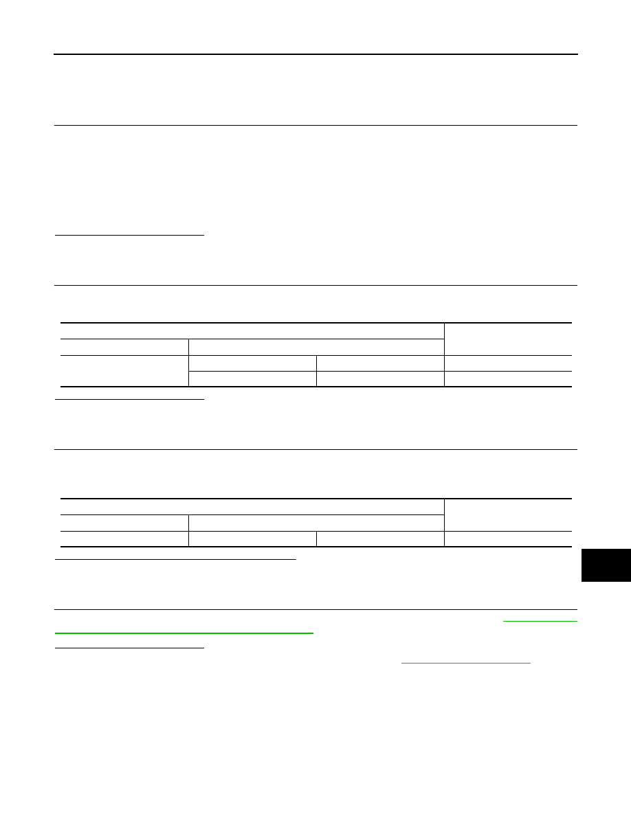
AFS control unit harness connector
Resistance (
Ω
)
Connector No.
Terminal No.
M16
30
7
Approx. 54 – 66
LAN
ICC BRANCH LINE CIRCUIT
LAN-165
< DTC/CIRCUIT DIAGNOSIS >
[CAN SYSTEM (TYPE 3)]
C
D
E
F
G
H
I
J
K
L
B
A
O
P
N
ICC BRANCH LINE CIRCUIT
Diagnosis Procedure
INFOID:0000000005576978
1.
CHECK CONNECTOR
1.
Turn the ignition switch OFF.
2.
Disconnect the battery cable from the negative terminal.
3.
Check the following terminals and connectors for damage, bend and loose connection (unit side and con-
nector side).
-
ICC sensor integrated unit
-
Harness connector E106
-
Harness connector M6
-
CAN gateway
Is the inspection result normal?
YES
>> GO TO 2.
NO
>> Repair the terminal and connector.
2.
CHECK HARNESS CONTINUITY (OPEN CIRCUIT)
1.
Disconnect the connector of CAN gateway.
2.
Check the continuity between the CAN gateway harness connector terminals.
Is the inspection result normal?
YES
>> GO TO 3.
NO
>> Check the harness and repair the root cause (CAN communication circuit 2).
3.
CHECK HARNESS FOR OPEN CIRCUIT
1.
Connect the connector of CAN gateway.
2.
Disconnect the connector of ICC sensor integrated unit.
3.
Check the resistance between the ICC sensor integrated unit harness connector terminals.
Is the measurement value within the specification?
YES
>> GO TO 4.
NO
>> Repair the ICC sensor integrated unit branch line.
4.
CHECK POWER SUPPLY AND GROUND CIRCUIT
Check the power supply and the ground circuit of the ICC sensor integrated unit. Refer to
SENSOR INTEGRATED UNIT : Diagnosis Procedure"
.
Is the inspection result normal?
YES (Present error)>>Replace the ICC sensor integrated unit. Refer to
.
YES (Past error)>>Error was detected in the ICC sensor integrated unit branch line.
NO
>> Repair the power supply and the ground circuit.
CAN gateway harness connector
Continuity
Connector No.
Terminal No.
M125
6
4
Existed
12
10
Existed
ICC sensor integrated unit harness connector
Resistance (
Ω
)
Connector No.
Terminal No.
E67
3
6
Approx. 54 – 66
Нет комментариевНе стесняйтесь поделиться с нами вашим ценным мнением.
Текст