Infiniti FX35, FX50 (S51). Manual — part 848
P0455 EVAP CONTROL SYSTEM
EC-933
< DTC/CIRCUIT DIAGNOSIS >
[VK50VE]
C
D
E
F
G
H
I
J
K
L
M
A
EC
N
P
O
EC-850, "Component Inspection"
Is the inspection result normal?
YES
>> GO TO 15.
NO
>> Replace “fuel level sensor unit and fuel pump (main)”.
15.
CHECK EVAP CONTROL SYSTEM PRESSURE SENSOR
EC-917, "Component Inspection"
Is the inspection result normal?
YES
>> GO TO 16.
NO
>> Replace EVAP control system pressure sensor.
16.
CHECK EVAP/ORVR LINE
Check EVAP/ORVR line between EVAP canister and fuel tank for clogging, kinks, looseness and improper
connection. For location, refer to
Is the inspection result normal?
YES
>> GO TO 17.
NO
>> Repair or replace hoses and tubes.
17.
CHECK RECIRCULATION LINE
Check recirculation line between filler neck tube and fuel tank for clogging, kinks, cracks, looseness and
improper connection.
Is the inspection result normal?
YES
>> GO TO 18.
NO
>> Repair or replace hose, tube or filler neck tube.
18.
CHECK REFUELING EVAP VAPOR CUT VALVE
EC-1124, "Component Inspection"
.
Is the inspection result normal?
YES
>> GO TO 19.
NO
>> Replace refueling EVAP vapor cut valve with fuel tank.
19.
CHECK INTERMITTENT INCIDENT
GI-36, "Intermittent Incident"
.
>> INSPECTION END
Component Inspection
INFOID:0000000005237398
1.
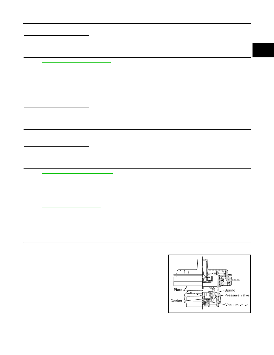
CHECK FUEL FILLER CAP
1.
Turn ignition switch OFF.
2.
Remove fuel filler cap.
3.
Wipe clean valve housing.
SEF445Y
EC-934
< DTC/CIRCUIT DIAGNOSIS >
[VK50VE]
P0455 EVAP CONTROL SYSTEM
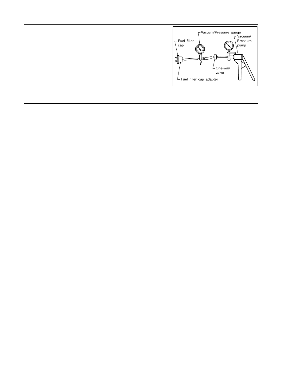
4.
Install fuel filler cap adapter (commercial service tool) to fuel
filler cap.
5.
Check valve opening pressure and vacuum.
Is the inspection result normal?
YES
>> INSPECTION END
NO
>> GO TO 2.
2.
REPLACE FUEL FILLER CAP
Replace fuel filler cap.
CAUTION:
Use only a genuine fuel filler cap as a replacement. If an incorrect fuel filler cap is used, the MIL may
illuminate.
>> INSPECTION END
Pressure:
15.3 - 20.0 kPa (0.156 - 0.204 kg/cm
2
, 2.22 -
2.90 psi)
Vacuum:
−
6.0 to
−
3.3 kPa (
−
0.061 to
−
0.034 kg/cm
2
,
−
0.87 to
−
0.48 psi)
SEF943S
P0456 EVAP CONTROL SYSTEM
EC-935
< DTC/CIRCUIT DIAGNOSIS >
[VK50VE]
C
D
E
F
G
H
I
J
K
L
M
A
EC
N
P
O
P0456 EVAP CONTROL SYSTEM
DTC Logic
INFOID:0000000005237399
DTC DETECTION LOGIC
NOTE:
If DTC P0456 is displayed with DTC P0442, first perform the trouble diagnosis for DTC P0456. Refer to
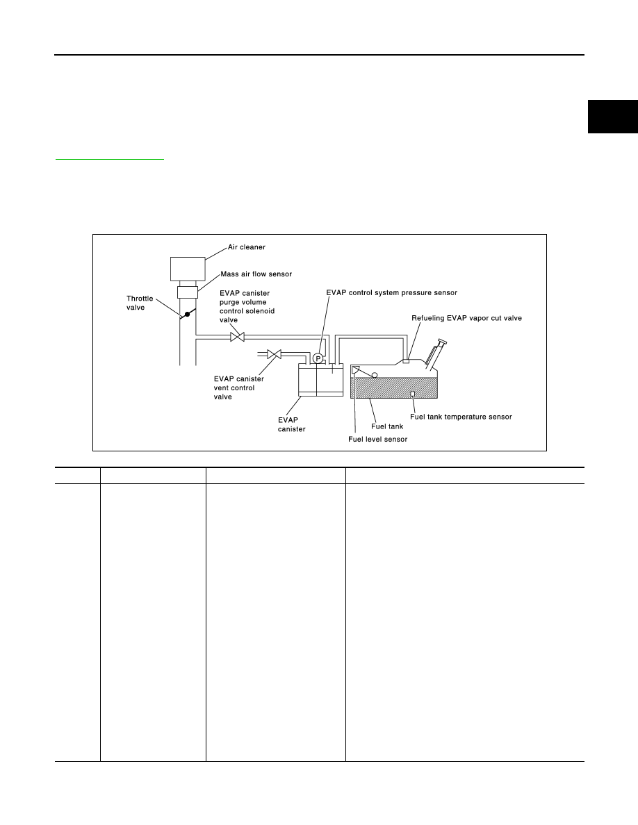
This diagnosis detects very small leaks in the EVAP line between fuel tank and EVAP canister purge volume
control solenoid valve, using the intake manifold vacuum in the same way as conventional EVAP small leak
diagnosis.
If ECM judges a leak which corresponds to a very small leak, the very small leak P0456 will be detected.
If ECM judges a leak equivalent to a small leak, EVAP small leak P0442 will be detected.
If ECM judges that there are no leaks, the diagnosis will be OK.
CAUTION:
PBIB1026E
DTC No.
Trouble diagnosis name
DTC detecting condition
Possible cause
P0456
Evaporative emission
control system very
small leak (negative
pressure check)
• EVAP system has a very small
leak.
• EVAP system does not operate
properly.
• Incorrect fuel tank vacuum relief valve
• Incorrect fuel filler cap used
• Fuel filler cap remains open or does not close.
• Foreign matter caught in fuel filler cap.
• Leak is in line between intake manifold and EVAP canis-
ter purge volume control solenoid valve.
• Foreign matter caught in EVAP canister vent control
valve.
• EVAP canister or fuel tank leaks
• EVAP purge line (pipe and rubber tube) leaks
• EVAP purge line rubber tube bent
• Loose or disconnected rubber tube
• EVAP canister vent control valve and the circuit
• EVAP canister purge volume control solenoid valve and
the circuit
• Fuel tank temperature sensor
• O-ring of EVAP canister vent control valve is missing or
damaged
• EVAP canister is saturated with water
• EVAP control system pressure sensor
• Refueling EVAP vapor cut valve
• ORVR system leaks
• Fuel level sensor and the circuit
• Foreign matter caught in EVAP canister purge volume
control solenoid valve
EC-936
< DTC/CIRCUIT DIAGNOSIS >
[VK50VE]
P0456 EVAP CONTROL SYSTEM
• Use only a genuine NISSAN fuel filler cap as a replacement. If an incorrect fuel filler cap is used, the
MIL may illuminate.
• If the fuel filler cap is not tightened properly, the MIL may illuminate.
• Use only a genuine NISSAN rubber tube as a replacement.
DTC CONFIRMATION PROCEDURE
1.
INSPECTION START
Will CONSULT-III be used?
Will CONSULT-III be used?
YES
>> GO TO 2.
NO
>> GO TO 4.
2.
PRECONDITIONING
If DTC Confirmation Procedure has been previously conducted, always perform the following procedure
before conducting the next test.
1.
Turn ignition switch OFF and wait at least 10 seconds.
2.
Turn ignition switch ON.
3.
Turn ignition switch OFF and wait at least 10 seconds.
NOTE:
After repair, check that the hoses and clips are installed properly.
TESTING CONDITION:
• Open engine hood before conducting the following procedure.
• If any of following conditions are met just before the DTC confirmation procedure, leave the vehicle
for more than 1 hour.
- Fuel filler cap is removed.
- Fuel is refilled or drained.
- EVAP component part/parts is/are removed.
• Before performing the following procedure, confirm that battery voltage is more than 11 V at idle.
• Check that EVAP hoses are connected to EVAP canister purge volume control solenoid valve prop-
erly.
>> GO TO 3.
3.
PERFORM DTC CONFIRMATION PROCEDURE
With CONSULT-III
1.
Turn ignition switch ON and select “DATA MONITOR” mode with CONSULT-III.
2.
Check that the following conditions are met.
FUEL LEVEL SE: 0.25 - 1.4 V
COOLAN TEMP/S: 0 - 32
°
C (32 - 90
°
F)
FUEL T/TMP SE: 0 - 35
°
C (32 - 95
°
F)
INT A/TEMP SE: More than 0
°
C (32
°
F)
If NG, turn ignition switch OFF and leave the vehicle in a cool place (soak the vehicle), or refill/drain fuel
until the output voltage of the “FUEL LEVEL SE” meets within the range above and leave the vehicle for
more than 1 hour. Then start from step 1.
3.
Turn ignition switch OFF and wait at least 10 seconds.
4.
Turn ignition switch ON.
5.
Select “EVP V/S LEAK P0456/P1456” of “EVAPORATIVE SYSTEM” in “DTC WORK SUPPORT” mode
with CONSULT-III.
Follow the instructions displayed.
NOTE:
If the engine speed cannot be maintained within the range displayed on CONSULT-III screen, go to
EC-576, "BASIC INSPECTION : Special Repair Requirement"
Which is displayed on CONSULT-III screen?
OK
>> INSPECTION END
NG
>> Go to
4.
PERFORM COMPONENT FUNCTION CHECK
With GST
Perform Component Function Check. Refer to
Нет комментариевНе стесняйтесь поделиться с нами вашим ценным мнением.
Текст