Infiniti FX35, FX50 (S51). Manual — part 208

BCS
SIGNAL BUFFER SYSTEM
BCS-13
< SYSTEM DESCRIPTION >
C
D
E
F
G
H
I
J
K
L
B
A
O
P
N
Interlock/PNP switch signal
TCM
IPDM E/R
Inputs the selector lever P/N po-
sition signal, and transmits the
interlock/PNP switch signal via
CAN communication.
Low tire pressure warning lamp
signal
Low tire pressure warning con-
trol unit
Combination meter (through
unified meter and A/C amp.)
(CAN)
Transmits the received low tire
pressure warning signal via
CAN communication.
Signal name
Input
Output
Description
BCS-14
< SYSTEM DESCRIPTION >
POWER CONSUMPTION CONTROL SYSTEM
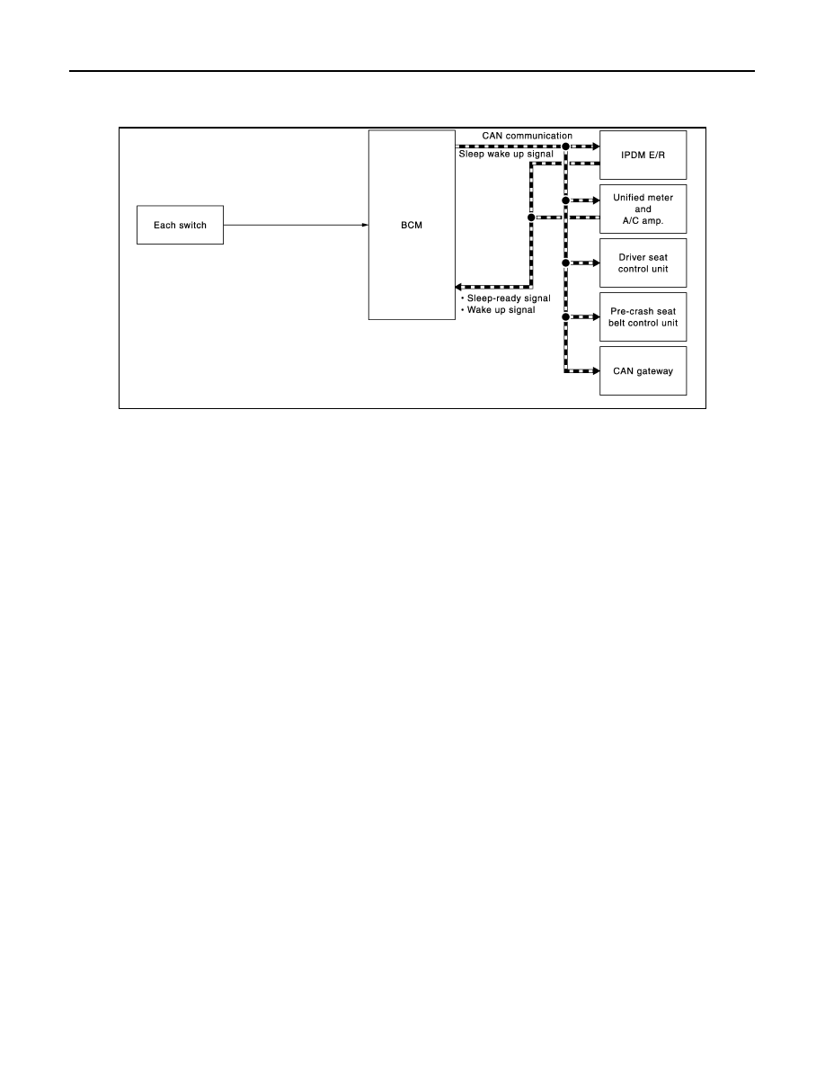
POWER CONSUMPTION CONTROL SYSTEM
System Diagram
INFOID:0000000005249306
System Description
INFOID:0000000005249307
OUTLINE
• BCM incorporates a power saving control function that reduces the power consumption according to the
vehicle status.
• BCM switches the status (control mode) by itself with the power saving control function. It performs the sleep
request to each unit [IPDM E/R, combination meter (unified meter and A/C amp.), driver seat control unit,
pre-crash seat belt control unit and CAN gateway] that operates with the ignition switch OFF.
Normal mode (wake-up)
- CAN communication is normally performed with other units
- Each control with BCM is operating properly
CAN communication sleep mode (CAN sleep)
- CAN transmission is stopped
- Control with BCM only is operating
Low power consumption mode (BCM sleep)
- Low power consumption control is active
- CAN transmission is stopped
LOW POWER CONSUMPTION CONTROL WITH BCM
BCM reduces the power consumption with the following operation in the low power consumption mode.
• The reading interval of the each switches changes from 10 ms interval to 60 ms interval.
Sleep mode activation
• BCM receives the sleep-ready signal (ready) from IPDM E/R and unified meter and A/C amp. via CAN com-
munication.
• BCM transmits the sleep wake up signal (sleep) to each unit when all of the CAN sleep conditions are ful-
filled.
• Each unit stops the transmission of CAN communication with the sleep wake up signal. BCM is in CAN com-
munication sleep mode.
• BCM is in the low power consumption mode and perform the low power consumption control when all of the
BCM sleep conditions are fulfilled with CAN sleep condition.
JMMIA0296GB

BCS
POWER CONSUMPTION CONTROL SYSTEM
BCS-15
< SYSTEM DESCRIPTION >
C
D
E
F
G
H
I
J
K
L
B
A
O
P
N
Sleep condition
Wake-up operation
• BCM changes from the low power consumption mode to the CAN communication sleep mode when the any
of the BCM wake-up conditions is fulfilled. Only the control with BCM is activated.
• BCM transmits the sleep wake up signal (wake up) to each unit when any of the CAN wake-up conditions is
fulfilled. It changes from the low power consumption mode or the CAN communication sleep mode to the
normal mode.
• Each unit starts the transmission of CAN communication with the sleep wake up signal. In addition, the uni-
fied meter and A/C amp. transmits the wake up signal to BCM via CAN communication to report the CAN
communication start.
Wake-up condition
CAN sleep condition
BCM sleep condition
• Receiving the sleep-ready signal (ready) from all units
• Ignition switch: OFF
• Vehicle security system and panic alarm: Not operation
• Warning chime: Not operation
• Intelligent Key system buzzer: Not operation
• Stop lamp switch: OFF
• ICC brake hold relay (with ICC): OFF
• Key slot (card switch) status: No change
• Turn signal indicator lamp: Not operation
• Exterior lamp: OFF
• Door lock status: No change
• CONSULT-III communication status: Not communication
• Meter display signal: Non-transmission
• Door switch status: No change
• Rear window defogger: OFF
• Interior room lamp battery saver: Time out
• RAP system: OFF
• Power window switch communication: No transmission
• Push-button ignition switch illumination: OFF
• Infiniti Vehicle Immobilizer System (IVIS) - NATS: Not operation
• Remote keyless entry receiver communication status: No com-
munication
• LOCK indicator lamp: OFF
• ACC indicator lamp: OFF
• ON indicator lamp: OFF
BCM wake-up condition
CAN wake-up condition
• Power window switch communication: Receiving
• Remote keyless entry receiver: Receiving
• Receiving the sleep-ready signal (Not-ready) from any units
• Key slot (key switch): OFF
→
ON, ON
→
OFF
• Push-button ignition switch (push switch): OFF
→
ON
• Hazard switch: OFF
→
ON
• PASSING switch: OFF
→
ON, ON
→
OFF
• TAIL LAMP switch: OFF
→
ON
• Driver door switch: OFF
→
ON, ON
→
OFF
• Passenger door switch: OFF
→
ON, ON
→
OFF
• Rear RH door switch: OFF
→
ON, ON
→
OFF
• Rear LH door switch: OFF
→
ON, ON
→
OFF
• Back door switch: OFF
→
ON, ON
→
OFF
• Driver door request switch: OFF
→
ON
• Passenger door request switch: OFF
→
ON
• Back door opener request switch: OFF
→
ON
• Stop lamp switch: ON
• ICC brake hold relay (with ICC): ON

BCS-16
< SYSTEM DESCRIPTION >
POWER CONSUMPTION CONTROL SYSTEM
Component Parts Location
INFOID:0000000005249308
1.
.
2.
BCM
Refer to
3.
.
4.
Unified meter and A/C amp.
Refer to
5.
Driver seat control unit
Refer to
DRIVE POSITIONER SYSTEM :
Component Parts Location"
6.
Pre-crash seat belt control unit
Refer to
.
JMMIA0297ZZ
Нет комментариевНе стесняйтесь поделиться с нами вашим ценным мнением.
Текст