Infiniti FX35, FX50 (S51). Manual — part 1801
A/T CONTROL SYSTEM
TM-11
< SYSTEM DESCRIPTION >
[7AT: RE7R01A (VQ35HR)]
C
E
F
G
H
I
J
K
L
M
A
B
TM
N
O
P
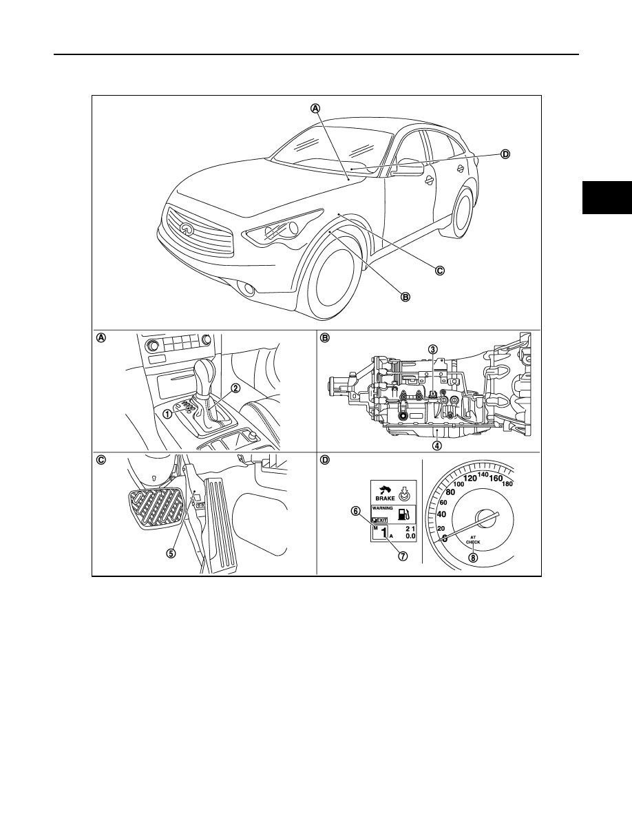
Component Parts Location
INFOID:0000000005249992
NOTE:
• The following components are included in A/T shift selector assembly.
- Manual mode select switch
- Manual mode position select switch
- Shift position switch
• The following components are included in control valve with TCM.
- TCM
- Input speed sensor 1, 2
- Output speed sensor
1.
Selector lever position indicator
2.
A/T shift selector assembly
3.
A/T assembly connector
4.
Control valve with TCM*
5.
Accelerator pedal position sensor
6.
Manual mode indicator
7.
Shift position indicator
8.
A/T CHECK indicator lamp
A.
Center console
B.
A/T assembly
C.
Accelerator pedal
D.
Combination meter
JSDIA0782ZZ

TM-12
< SYSTEM DESCRIPTION >
[7AT: RE7R01A (VQ35HR)]
A/T CONTROL SYSTEM
- A/T fluid temperature sensor
- Transmission range switch
- Direct clutch solenoid valve
- High and low reverse clutch solenoid valve
- Input clutch solenoid valve
- Front brake solenoid valve
- Low brake solenoid valve
- Anti-interlock solenoid valve
- 2346 brake solenoid valve
- Line pressure solenoid valve
- Torque converter clutch solenoid valve
*: Control valve with TCM is included in A/T assembly.
Component Description
INFOID:0000000005249993
Name
Function
TCM
The TCM consists of a microcomputer and connectors for signal input and output and
for power supply. The TCM controls the A/T.
Transmission range switch
Output speed sensor
Input speed sensor 1
Input speed sensor 2
A/T fluid temperature sensor
Input clutch solenoid valve
Front brake solenoid valve
Direct clutch solenoid valve
High and low reverse clutch solenoid valve
Low brake solenoid valve
Anti-interlock solenoid valve
2346 brake solenoid valve
Line pressure solenoid valve
Torque converter clutch solenoid valve
Accelerator pedal position sensor
Manual mode switch
Starter relay
A/T CHECK indicator lamp
When the ignition switch is pushed to the ON position, the light comes on for 2 seconds.
Stop lamp switch
ECM
BCM
Unified meter and A/C amp.
MWI-6, "METER SYSTEM : System Description"
ABS actuator and electric unit (control unit)
Yaw rate/side G sensor
LINE PRESSURE CONTROL
TM-13
< SYSTEM DESCRIPTION >
[7AT: RE7R01A (VQ35HR)]
C
E
F
G
H
I
J
K
L
M
A
B
TM
N
O
P
LINE PRESSURE CONTROL
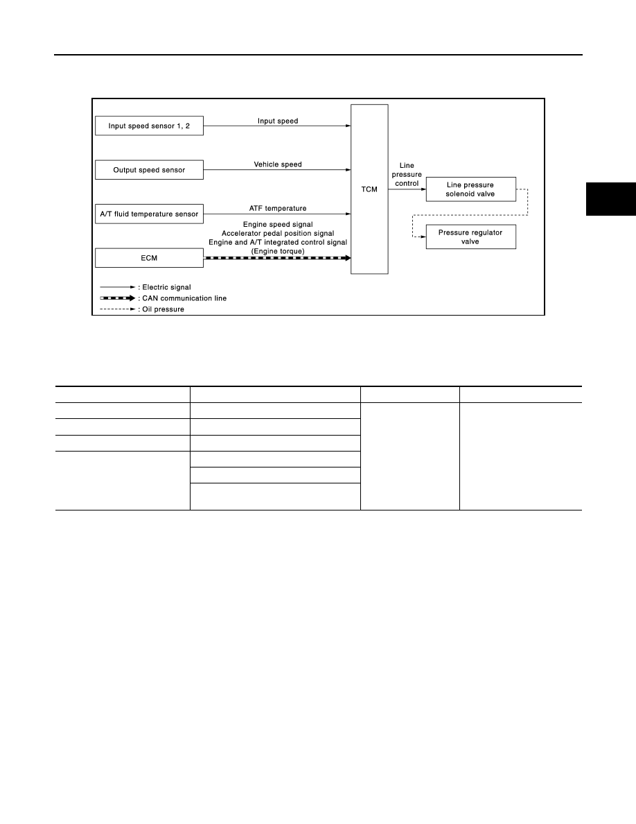
System Diagram
INFOID:0000000005249994
System Description
INFOID:0000000005249995
INPUT/OUTPUT SIGNAL CHART
*: This signal is transmitted via CAN communication line.
SYSTEM DESCRIPTION
• When an engine and A/T integrated control signal (engine torque) equivalent to the engine drive force is
transmitted from the ECM to the TCM, the TCM controls the line pressure solenoid valve.
This line pressure solenoid controls the pressure regulator valve as the signal pressure and adjusts the pres-
sure of the operating oil discharged from the oil pump to the line pressure most appropriate to the driving
state.
• The TCM has stored in memory a number of patterns for the optimum line pressure characteristic for the
driving state.
• In order to obtain the most appropriate line pressure characteristic to meet the current driving state, the TCM
controls the line pressure solenoid current value and thus controls the line pressure.
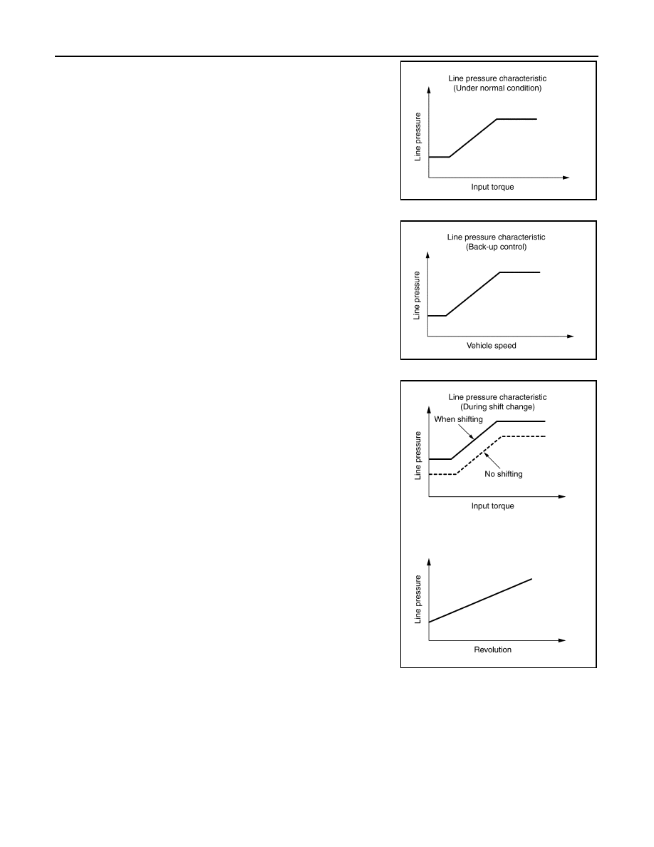
Normal Control
JSDIA1345GB
Sensor
Input signal to TCM
TCM function
Actuator
Input speed sensor 1, 2
Input speed
Line pressure control
Line pressure solenoid valve
↓
Pressure regulator valve
Output speed sensor
Vehicle speed
A/T fluid temperature sensor
ATF temperature
ECM
Engine speed signal*
Accelerator pedal position signal*
Engine and A/T integrated control signal
(Engine torque)*
TM-14
< SYSTEM DESCRIPTION >
[7AT: RE7R01A (VQ35HR)]
LINE PRESSURE CONTROL
Each clutch is adjusted to the necessary pressure to match the
engine drive force.
Back-up Control (Engine Brake)
When the select operation is performed during driving and the A/T is
shifted down, the line pressure is set according to the vehicle speed.
During Shift Change
The necessary and adequate line pressure for shift change is set.
For this reason, line pressure pattern setting corresponds to engine
torque and gearshift selection. Also, line pressure characteristic cor-
responds to engine speed, during engine brake operation.
At Low Fluid Temperature
PCIA0008E
PCIA0009E
PCIA0010E
Нет комментариевНе стесняйтесь поделиться с нами вашим ценным мнением.
Текст