Infiniti FX35, FX50 (S51). Manual — part 390
CCS-380
< REMOVAL AND INSTALLATION >
[DCA]
ICC SENSOR INTEGRATED UNIT
REMOVAL AND INSTALLATION
ICC SENSOR INTEGRATED UNIT
Exploded View
INFOID:0000000005502019
CAUTION:
Always perform the laser beam aiming adjustment and check the operation after the replacement,
removal and installation of ICC sensor integrated unit.
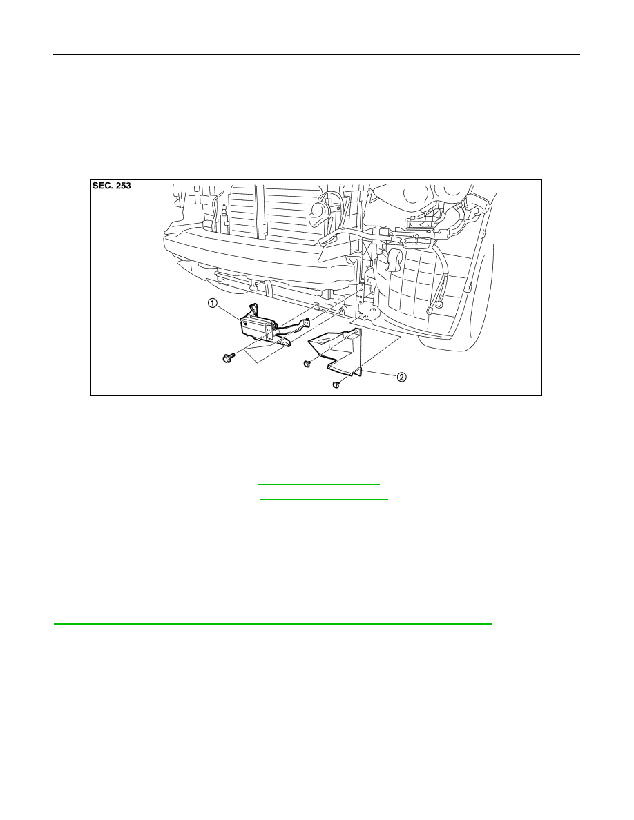
Removal and Installation
INFOID:0000000005502020
REMOVAL
1.
Remove front bumper fascia. Refer to
2.
Remove air guide lower (LH). Refer to
.
3.
Disconnect ICC sensor integrated unit connector.
4.
Remove mounting bolts from ICC sensor integrated unit.
5.
Remove ICC sensor integrated unit.
INSTALLATION
Install in the reverse order of removal.
CAUTION:
Always perform the laser beam aiming adjustment and check the operation after the replacement,
removal, and installation of ICC sensor integrated unit. Refer to
WHEN REPLACING CONTROL UNIT (ICC SENSOR INTEGRATED UNIT) : Description"
1.
ICC sensor integrated unit
2.
Air guide lower (LH)
JPOIA0190ZZ
CCS
BRAKE BOOSTER CONTROL UNIT
CCS-381
< REMOVAL AND INSTALLATION >
[DCA]
C
D
E
F
G
H
I
J
K
L
M
B
N
P
A
BRAKE BOOSTER CONTROL UNIT
Exploded View
INFOID:0000000005502021
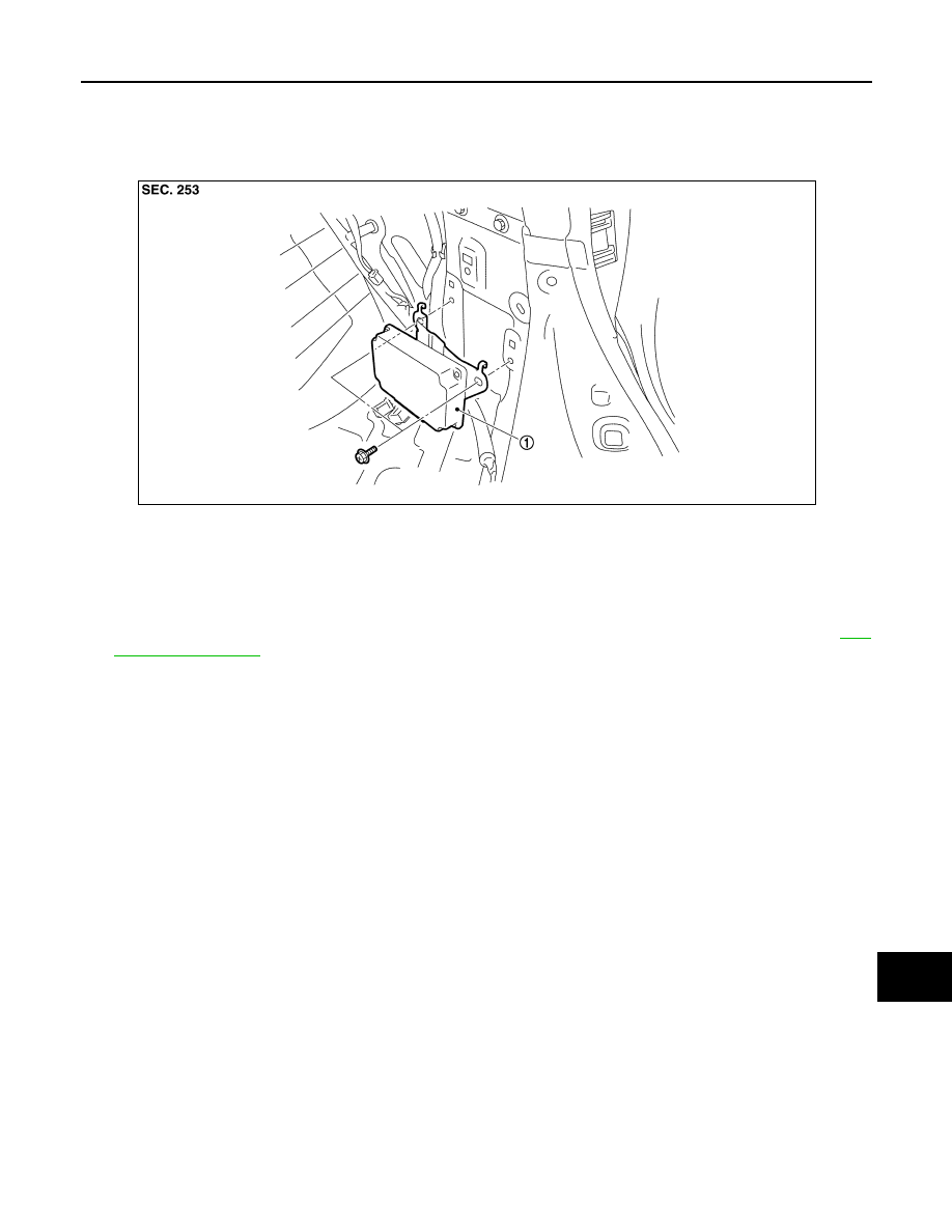
Removal and Installation
INFOID:0000000005502022
REMOVAL
1.
Remove clips on the back of the luggage side finisher lower (RH) to obtain space for work. Refer to
2.
Disconnect brake booster control unit connector.
3.
Remove mounting bolts from brake booster control unit.
4.
Remove brake booster control unit.
INSTALLATION
Install in the reverse order of removal.
1.
Brake booster control unit
JPOIA0193ZZ
CCS-382
< REMOVAL AND INSTALLATION >
[DCA]
ICC WARNING CHIME
ICC WARNING CHIME
Exploded View
INFOID:0000000005502023
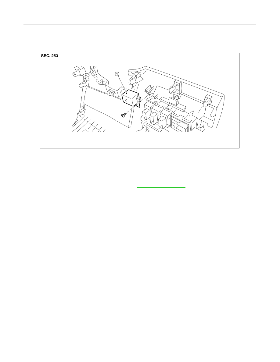
Removal and Installation
INFOID:0000000005502024
REMOVAL
1.
Remove the instrument lower panel LH. Refer to
2.
Remove mounting screw from ICC warning chime.
3.
Remove ICC warning chime from the instrument lower panel LH.
INSTALLATION
Install in the reverse order of removal.
1.
ICC warning chime
JPOIA0191ZZ

CCS
ACCELERATOR PEDAL ASSEMBLY
CCS-383
< REMOVAL AND INSTALLATION >
[DCA]
C
D
E
F
G
H
I
J
K
L
M
B
N
P
A
ACCELERATOR PEDAL ASSEMBLY
Exploded View
INFOID:0000000005502025
ACC-4, "MODELS WITH DISTANCE CONTROL ASSIST SYSTEM : Exploded View"
CAUTION:
Always perform accelerator pedal released position learning after replacement, removal, or installa-
tion of accelerator pedal assembly, and then check the DCA system operation. Refer to
"ADDITIONAL SERVICE WHEN REPLACING CONTROL UNIT (ACCELERATOR PEDAL ASSEMBLY) :
Description"
Нет комментариевНе стесняйтесь поделиться с нами вашим ценным мнением.
Текст