Infiniti FX35, FX50 (S51). Manual — part 553

AWD WARNING LAMP BLINKS SLOWLY
DLN-47
< SYMPTOM DIAGNOSIS >
[TRANSFER: ETX13C]
C
E
F
G
H
I
J
K
L
M
A
B
DLN
N
O
P
AWD WARNING LAMP BLINKS SLOWLY
Description
INFOID:0000000005249089
AWD warning lamp blinks at approximately 2 seconds intervals while driving.
Diagnosis Procedure
INFOID:0000000005249090
1.
CHECK TIRE
Check the following.
• Tire pressure
• Wear condition
• Front and rear tire size (There is no difference between front and rear tires.)
Is the inspection result normal?
YES
>> GO TO 2.
NO
>> Repair or replace error-detected parts. And then, drive the vehicle at speed of 20 km/h (12 MPH)
or more for 5 seconds or more. Improper size information is initialized accordingly.
2.
CHECK INPUT SIGNAL OF TIRE DIAMETER
With CONSULT-III
1.
Start the engine.
2.
Drive at 20 km/h (12 MPH) or more for approximately 4 minutes.
3.
Check “DIS-TIRE MONI” of CONSULT-III “DATA MONITOR” for “ALL MODE AWD/4WD”.
Does the item on “DATA MONITOR” indicate “0 - 4 mm”?
YES
>> INSPECTION END
NO
>> GO TO 3.
3.
TERMINAL INSPECTION
Check AWD control unit harness connector for disconnection.
Is the inspection result normal?
YES
>> Replace AWD control unit. Refer to
NO
>> Repair or replace the error-detected parts.
DLN-48
< SYMPTOM DIAGNOSIS >
[TRANSFER: ETX13C]
NOISE, VIBRATION AND HARSHNESS (NVH) TROUBLESHOOTING
NOISE, VIBRATION AND HARSHNESS (NVH) TROUBLESHOOTING
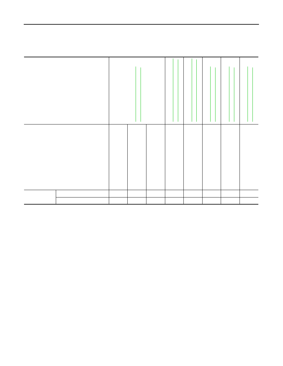
NVH Troubleshooting Chart
INFOID:0000000005249091
Use the chart below to find the cause of the symptom. The numbers indicate the order of the inspection. If necessary, repair or replace these
parts.
Reference
SUSPECTED PARTS
(Possible cause)
TRANSFE
R
FLUI
D
(Level
lo
w)
TRANSFE
R
FLUI
D
(W
rong)
TRANSFE
R
FLUI
D (Le
v
e
l
too hi
gh)
LIQUID GA
SKET
(Damaged)
OIL SEAL (W
orn or
damaged)
GEAR (W
orn
or
da
ma
ge
d)
BEARING (W
orn or damaged)
TRANSFE
R
CASE
(Damaged)
Symptom
Noise
1
2
3
3
3
Transfer fluid leakage
4
1
2
2
3
PRECAUTIONS
DLN-49
< PRECAUTION >
[TRANSFER: ETX13C]
C
E
F
G
H
I
J
K
L
M
A
B
DLN
N
O
P
PRECAUTION
PRECAUTIONS
Precaution for Supplemental Restraint System (SRS) "AIR BAG" and "SEAT BELT
PRE-TENSIONER"
INFOID:0000000005249092
The Supplemental Restraint System such as “AIR BAG” and “SEAT BELT PRE-TENSIONER”, used along
with a front seat belt, helps to reduce the risk or severity of injury to the driver and front passenger for certain
types of collision. This system includes seat belt switch inputs and dual stage front air bag modules. The SRS
system uses the seat belt switches to determine the front air bag deployment, and may only deploy one front
air bag, depending on the severity of a collision and whether the front occupants are belted or unbelted.
Information necessary to service the system safely is included in the “SRS AIR BAG” and “SEAT BELT” of this
Service Manual.
WARNING:
• To avoid rendering the SRS inoperative, which could increase the risk of personal injury or death in
the event of a collision which would result in air bag inflation, all maintenance must be performed by
an authorized NISSAN/INFINITI dealer.
• Improper maintenance, including incorrect removal and installation of the SRS, can lead to personal
injury caused by unintentional activation of the system. For removal of Spiral Cable and Air Bag
Module, see the “SRS AIR BAG”.
• Do not use electrical test equipment on any circuit related to the SRS unless instructed to in this
Service Manual. SRS wiring harnesses can be identified by yellow and/or orange harnesses or har-
ness connectors.
PRECAUTIONS WHEN USING POWER TOOLS (AIR OR ELECTRIC) AND HAMMERS
WARNING:
• When working near the Air Bag Diagnosis Sensor Unit or other Air Bag System sensors with the
ignition ON or engine running, DO NOT use air or electric power tools or strike near the sensor(s)
with a hammer. Heavy vibration could activate the sensor(s) and deploy the air bag(s), possibly
causing serious injury.
• When using air or electric power tools or hammers, always switch the ignition OFF, disconnect the
battery, and wait at least 3 minutes before performing any service.
Precaution Necessary for Steering Wheel Rotation after Battery Disconnect
INFOID:0000000005249093
NOTE:
• Before removing and installing any control units, first turn the push-button ignition switch to the LOCK posi-
tion, then disconnect both battery cables.
• After finishing work, confirm that all control unit connectors are connected properly, then re-connect both
battery cables.
• Always use CONSULT-III to perform self-diagnosis as a part of each function inspection after finishing work.
If a DTC is detected, perform trouble diagnosis according to self-diagnosis results.
For vehicle with steering lock unit, if the battery is disconnected or discharged, the steering wheel will lock and
cannot be turned.
If turning the steering wheel is required with the battery disconnected or discharged, follow the operation pro-
cedure below before starting the repair operation.
OPERATION PROCEDURE
1.
Connect both battery cables.
NOTE:
Supply power using jumper cables if battery is discharged.
2.
Turn the push-button ignition switch to ACC position.
(At this time, the steering lock will be released.)
3.
Disconnect both battery cables. The steering lock will remain released with both battery cables discon-
nected and the steering wheel can be turned.
4.
Perform the necessary repair operation.
DLN-50
< PRECAUTION >
[TRANSFER: ETX13C]
PRECAUTIONS
5.
When the repair work is completed, re-connect both battery cables. With the brake pedal released, turn
the push-button ignition switch from ACC position to ON position, then to LOCK position. (The steering
wheel will lock when the push-button ignition switch is turned to LOCK position.)
6.
Perform self-diagnosis check of all control units using CONSULT-III.
Service Notice or Precautions for Transfer
INFOID:0000000005249094
CAUTION:
• Never reuse transfer fluid, once it has been drained.
• Check the fluid level or replace the fluid only with the vehicle parked on level ground.
• During removal or installation, keep inside of transfer clear of dust or dirt.
• Replace all tires at the same time. Always use tires of the proper size and the same brand and pat-
tern. Fitting improper size and unusually worn tires applies excessive force to vehicle mechanism
and can cause longitudinal vibration.
• Disassembly should be done in a clean work area, it is preferable to work in dustproof area.
• Before proceeding with disassembly, thoroughly clean the transfer. It is important to prevent the
internal parts from becoming contaminated by dirt or other foreign matter.
• All parts should be carefully cleaned with a general purpose, non-flammable solvent before inspec-
tion or reassembly.
• Check for the correct installation status prior to removal or disassembly. If matching marks are
required, be certain they do not interfere with the function of the parts when applied.
• Check appearance of the disassembled parts for damage, deformation, and unusual wear. Replace
them with a new ones if necessary.
• Gaskets, seals and O-rings should be replaced any time the transfer is disassembled.
• In principle, tighten bolts or nuts gradually in several steps working diagonally from inside to out-
side. If tightening sequence is specified, use it.
• Observe the specified torque when assembling.
• Clean and flush the parts sufficiently and blow-dry them.
• Be careful not to damage sliding surfaces and mating surfaces.
• Clean inner parts with lint-free cloth or towels. Do not use cotton work gloves and rags to prevent
adhering fibers.
Нет комментариевНе стесняйтесь поделиться с нами вашим ценным мнением.
Текст