Infiniti FX35, FX50 (S51). Manual — part 664

P0127 IAT SENSOR
EC-197
< DTC/CIRCUIT DIAGNOSIS >
[VQ35HR]
C
D
E
F
G
H
I
J
K
L
M
A
EC
N
P
O
-
If the engine coolant temperature is not less than 96
°
C (205
°
F), turn ignition switch OFF and cool down
engine.
NOTE:
Perform the following steps before engine coolant temperature is above 96
°
C (205
°
F).
2.
Turn ignition switch ON.
3.
Select “DATA MONITOR” mode with CONSULT-III.
4.
Start engine.
5.
Hold vehicle speed at more than 70 km/h (43 MPH) for 100 consecutive seconds.
CAUTION:
Always drive vehicle at a safe speed.
6.
Check 1st trip DTC.
With GST
Follow the procedure “With CONSULT-III” above.
Is 1st trip DTC detected?
YES
>> Go to
NO
>> INSPECTION END
Diagnosis Procedure
INFOID:0000000005236801
1.
CHECK GROUND CONNECTION
1.
Turn ignition switch OFF.
2.
Check ground connection M95. Refer to Ground Inspection in
Is the inspection result normal?
YES
>> GO TO 2.
NO
>> Repair or replace ground connection.
2.
CHECK INTAKE AIR TEMPERATURE SENSOR
EC-197, "Component Inspection"
Is the inspection result normal?
YES
>> GO TO 3.
NO
>> Replace mass air flow sensor (bank 1) (with intake air temperature sensor).
3.
CHECK INTERMITTENT INCIDENT
GI-36, "Intermittent Incident"
.
>> INSPECTION END
Component Inspection
INFOID:0000000005236802
1.
CHECK INTAKE AIR TEMPERATURE SENSOR
1.
Turn ignition switch OFF.
2.
Disconnect mass air flow sensor (bank 1) harness connector.
3.
Check resistance between mass air flow sensor (bank 1) terminals as follows.
Is the inspection result normal?
YES
>> INSPECTION END
NO
>> Replace mass air flow sensor (with intake air temperature sensor) (bank 1).
Terminals
Condition
Resistance (k
Ω
)
1 and 2
Temperature [
°
C (
°
F)]
25 (77)
1.800 - 2.200

EC-198
< DTC/CIRCUIT DIAGNOSIS >
[VQ35HR]
P0128 THERMOSTAT FUNCTION
P0128 THERMOSTAT FUNCTION
DTC Logic
INFOID:0000000005236803
DTC DETECTION LOGIC
NOTE:
If DTC P0128 is displayed with DTC P0300, P0301, P0302, P0303, P0304, P0305 or P0306, first perform the
trouble diagnosis for DTC P0300, P0301, P0302, P0303, P0304, P0305, P0306. Refer to
.
Engine coolant temperature has not risen enough to open the thermostat even though the engine has run long
enough.
This is due to a leak in the seal or the thermostat being stuck open.
DTC CONFIRMATION PROCEDURE
1.
PRECONDITIONING
If DTC Confirmation Procedure has been previously conducted, always perform the following procedure
before conducting the next test.
1.
Turn ignition switch OFF and wait at least 10 seconds.
2.
Turn ignition switch ON.
3.
Turn ignition switch OFF and wait at least 10 seconds.
TESTING CONDITION:
• For best results, perform at ambient temperature of –10
°
C (14
°
F) or higher.
• For best results, perform at engine coolant temperature of –10
°
C (14
°
F) to 56
°
C (133
°
F).
• Before performing the following procedure, do not add fuel.
>> GO TO 2.
2.
PERFORM DTC CONFIRMATION PROCEDURE
With CONSULT-III
1.
Turn A/C switch OFF.
2.
Turn blower fan switch OFF.
3.
Turn ignition switch ON.
4.
Select “COOLAN TEMP/S” in “DATA MONITOR” mode with CONSULT-III.
5.
Check the indication of “COOLAN TEMP/S”.
If it is below 56
°
C (133
°
F), go to the next step.
If it is above 56
°
C (133
°
F), cool engine down to less than 56
°
C (133
°
F). Then go to next step.
6.
Start engine and drive vehicle for 10 consecutive minutes under the following conditions.
CAUTION:
Always drive vehicle at a safe speed.
NOTE:
If “COOLAN TEMP/S” increases to more than 75
°
C (167
°
F) with in 30 minutes, turn ignition switch
OFF because the test result will be OK.
7.
Check 1st trip DTC.
With GST
Follow the procedure “With CONSULT-III” above.
Is 1st trip DTC detected?
YES
>> Go to
NO
>> INSPECTION END
DTC No.
Trouble diagnosis name
DTC detecting condition
Possible cause
P0128
Thermostat function
The engine coolant temperature does not reach
to specified temperature even though the en-
gine has run long enough.
• Thermostat
• Leakage from sealing portion of thermo-
stat
• Engine coolant temperature sensor
VHCL SPEED SE
More than 56 km/h (35 MPH)
P0128 THERMOSTAT FUNCTION
EC-199
< DTC/CIRCUIT DIAGNOSIS >
[VQ35HR]
C
D
E
F
G
H
I
J
K
L
M
A
EC
N
P
O
Diagnosis Procedure
INFOID:0000000005236804
1.
CHECK ENGINE COOLANT TEMPERATURE SENSOR
EC-199, "Component Inspection"
Is the inspection result normal?
YES
>> INSPECTION END
NO
>> Replace engine coolant temperature sensor.
Component Inspection
INFOID:0000000005236805
1.
CHECK ENGINE COOLANT TEMPERATURE SENSOR
1.
Turn ignition switch OFF.
2.
Disconnect engine coolant temperature sensor harness connector.
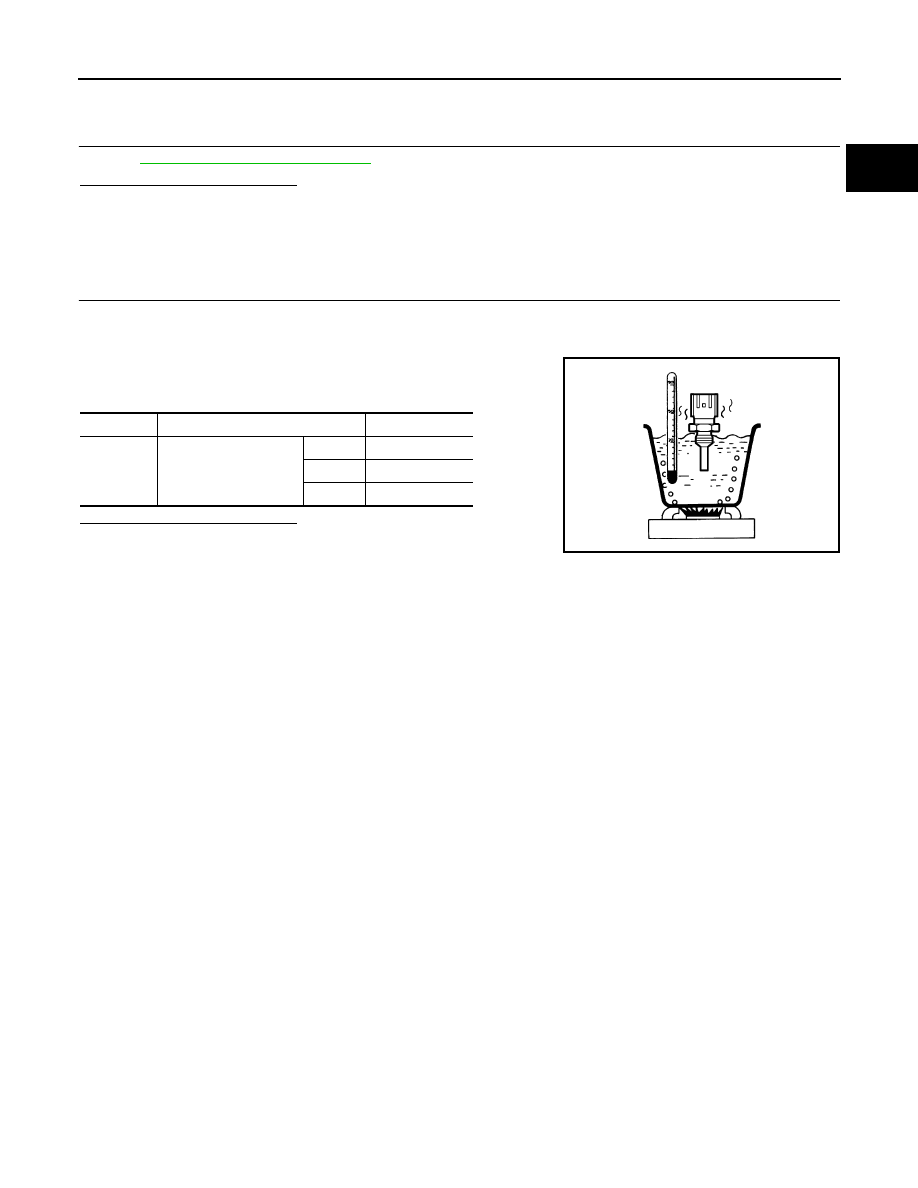
3.
Remove engine coolant temperature sensor.
4.
Check resistance between engine coolant temperature sensor
terminals by heating with hot water as shown in the figure.
Is the inspection result normal?
YES
>> INSPECTION END
NO
>> Replace engine coolant temperature sensor.
Terminals
Condition
Resistance (k
Ω
)
1 and 2
Temperature [
°
C (
°
F)]
20 (68)
2.37 - 2.63
50 (122)
0.68 - 1.00
90 (194)
0.236 - 0.260
JMBIA0080ZZ
EC-200
< DTC/CIRCUIT DIAGNOSIS >
[VQ35HR]
P0130, P0150 A/F SENSOR 1
P0130, P0150 A/F SENSOR 1
Description
INFOID:0000000005236806
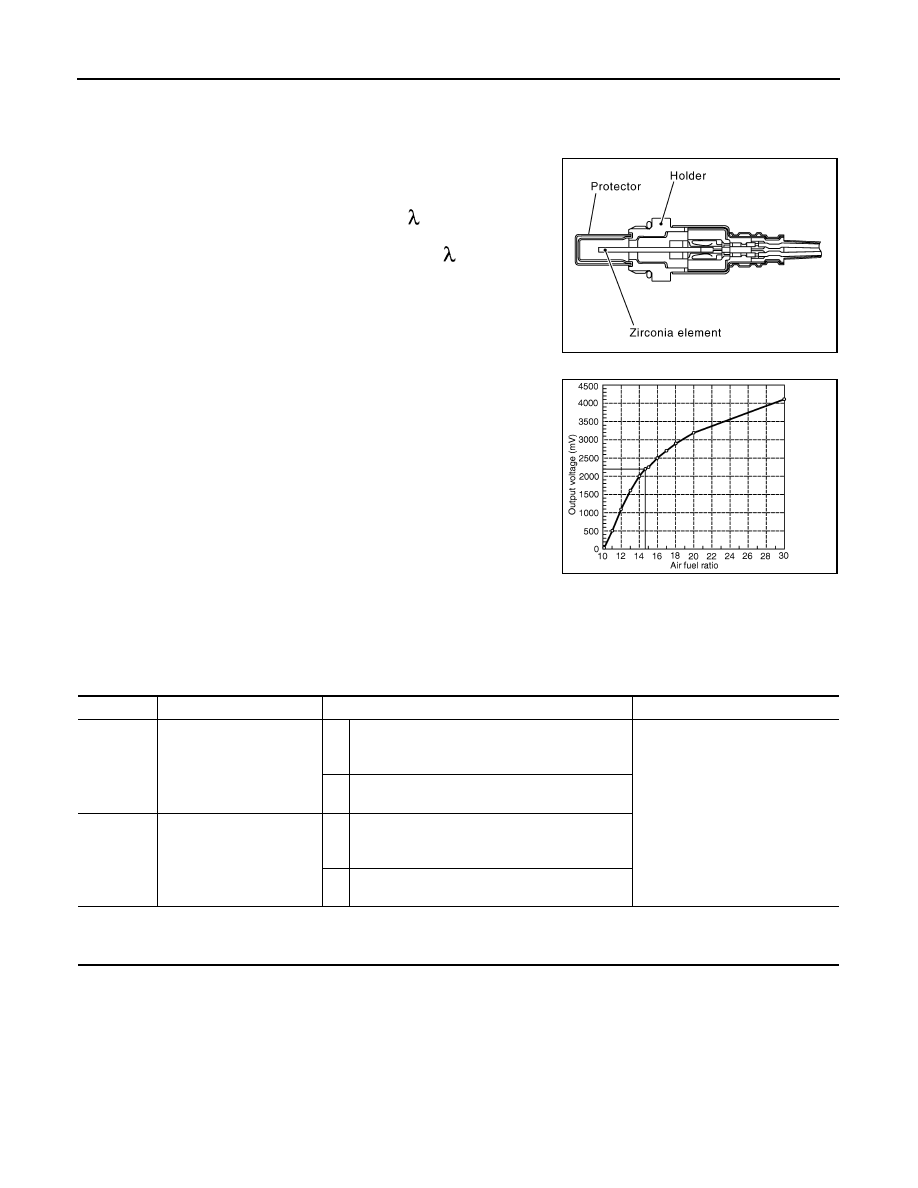
The air fuel ratio (A/F) sensor 1 is a planar one-cell limit current sen-
sor. The sensor element of the A/F sensor 1 is composed an elec-
trode layer, which transports ions. It has a heater in the element.
The sensor is capable of precise measurement = 1, but also in the
lean and rich range. Together with its control electronics, the sensor
outputs a clear, continuous signal throughout a wide range.
The exhaust gas components diffuse through the diffusion layer at
the sensor cell. An electrode layer is applied voltage, and this current
relative oxygen density in lean. Also this current relative hydrocar-
bon density in rich.
Therefore, the A/F sensor 1 is able to indicate air fuel ratio by this
electrode layer of current. In addition, a heater is integrated in the
sensor to ensure the required operating temperature of approxi-
mately 800
°
C (1,472
°
F).
DTC Logic
INFOID:0000000005236807
DTC DETECTION LOGIC
To judge malfunctions, the diagnosis checks that the air fuel ratio (A/F) signal computed by ECM from the A/F
sensor 1 signal fluctuates according to fuel feedback control.
DTC CONFIRMATION PROCEDURE
1.
PRECONDITIONING
If DTC Confirmation Procedure has been previously conducted, always perform the following procedure
before conducting the next test.
1.
Turn ignition switch OFF and wait at least 10 seconds.
2.
Turn ignition switch ON.
3.
Turn ignition switch OFF and wait at least 10 seconds.
TESTING CONDITION:
Before performing the following procedure, confirm that battery voltage is more than 11 V at idle.
>> GO TO 2.
JMBIA0112GB
PBIB3354E
DTC No.
Trouble diagnosis name
DTC detecting condition
Possible Cause
P0130
Air fuel ratio (A/F) sensor 1
(bank 1) circuit
A)
The A/F signal computed by ECM from the A/F
sensor 1 signal is constantly in a range other
than approx. 2.2 V.
• Harness or connectors
(The A/F sensor 1 circuit is open
or shorted.)
• A/F sensor 1
B)
The A/F signal computed by ECM from the A/F
sensor 1 signal is constantly approx. 2.2 V.
P0150
Air fuel ratio (A/F) sensor 1
(bank 2) circuit
A)
The A/F signal computed by ECM from the A/F
sensor 1 signal is constantly in a range other
than approx. 2.2 V.
B)
The A/F signal computed by ECM from the A/F
sensor 1 signal is constantly approx. 2.2 V.
Нет комментариевНе стесняйтесь поделиться с нами вашим ценным мнением.
Текст