Infiniti FX35, FX50 (S51). Manual — part 356

CCS-244
< DTC/CIRCUIT DIAGNOSIS >
[DCA]
C1A13 STOP LAMP RELAY
NO
>> Repair the harnesses or connectors.
18.
CHECK ICC BRAKE HOLD RELAY
1.
Connect ECM, rear combination lamp, and high-mounted stop lamp connectors and ICC brake hold relay.
2.
Disconnect the stop lamp switch connector.
3.
Turn ignition switch ON.
4.
Perform “STOP LAMP” on “Active Test” of “ICC”, and then check the stop lamp for illumination.
Is the inspection result normal?
YES
>> GO TO 19.
NO
>> Replace ICC brake hold relay.
19.
CHECK ICC BRAKE SWITCH STANDARD VOLTAGE
1.
Turn ignition switch OFF.
2.
Connect the stop lamp switch connector.
3.
Turn ignition switch ON.
4.
Perform “STOP LAMP” on “Active Test” of “ICC”, and then check the voltage between ICC brake switch
harness connector and ground.
Is the inspection result normal?
YES
>> GO TO 20.
NO
>> Replace ICC brake hold relay.
20.
PERFORM SELF-DIAGNOSIS OF ECM
1.
Connect all connectors again if the connectors are disconnected.
2.
Turn ignition switch ON.
3.
Perform “All DTC Reading”.
4.
Check if any DTC is detected in “Self Diagnostic Result” of “ENGINE”. Refer to
(VK50VE).
Is any DTC detected?
YES
>> Repair or replace the malfunctioning parts identified by the self-diagnosis result.
NO
>> GO TO 21.
21.
CHECK ICC BRAKE HOLD RELAY DRIVE SIGNAL OUTPUT
1.
Select the active test item “STOP LAMP” of “ICC”.
2.
Check that “STP LMP DRIVE” is turned ON when operating the test item.
Is the inspection result normal?
YES
>> Replace brake booster control unit.
NO
>> Replace the ICC sensor integrated unit. Refer to
Component Inspection
INFOID:0000000005501833
1.
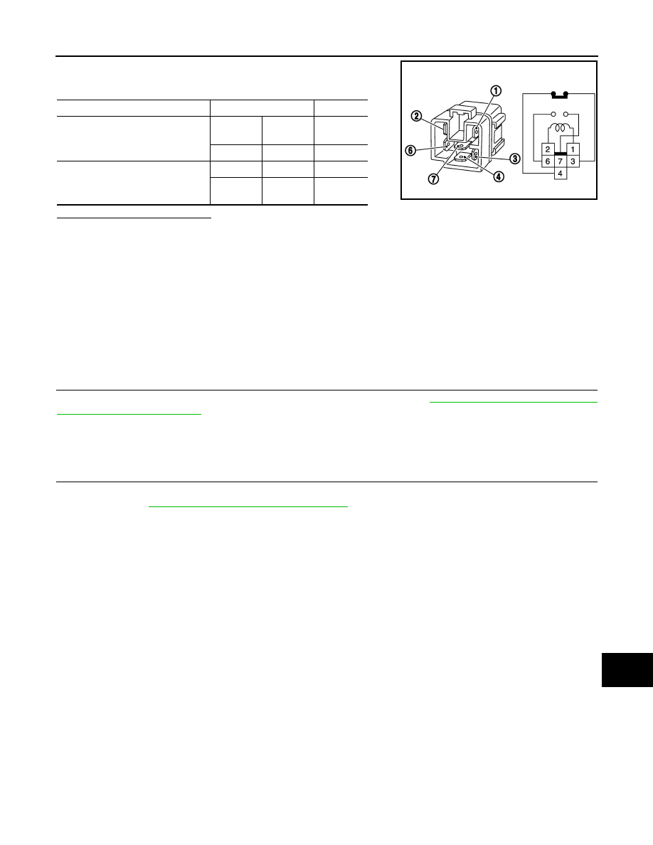
CHECK ICC BRAKE HOLD RELAY
Terminal
Condition
Voltage
(Approx.)
(+)
(–)
ICC brake switch
Ground
Active Test
item
“STOP LAMP”
Connector
Terminal
E114
1
Off
Battery
voltage
On
0 V
CCS
C1A13 STOP LAMP RELAY
CCS-245
< DTC/CIRCUIT DIAGNOSIS >
[DCA]
C
D
E
F
G
H
I
J
K
L
M
B
N
P
A
Apply battery voltage to ICC brake hold relay terminals 1 and 2, and
then check for continuity under the following conditions.
Is the inspection result normal?
YES
>> INSPECTION END
NO
>> Replace ICC brake hold relay.
Special Repair Requirement
INFOID:0000000005501834
DESCRIPTION
Perform the action test after adjusting the laser beam aiming of ICC sensor integrated unit when the following
operation is performed.
• Removal and installation of ICC sensor integrated unit
• Replacement of ICC sensor integrated unit
SPECIAL REPAIR REQUIREMENT
1.
LASER BEAM AIMING ADJUSTMENT OF ICC SENSOR INTEGRATED UNIT
Adjust the laser beam aiming of the ICC sensor integrated unit. Refer to
>> GO TO 2.
2.
CHECK DCA SYSTEM
1.
Erase the “self-diagnosis results”, and then perform “All DTC Reading” again after performing the action
test. (Refer to
CCS-191, "ACTION TEST : Description"
for action test.)
2.
Check that the DCA system is normal.
>> WORK END
Condition
Terminal
Continuity
When the battery voltage is applied
3
4
Not exist-
ed
7
6
Existed
When the battery voltage is not ap-
plied
3
4
Existed
7
6
Not exist-
ed
MBIB0063E

CCS-246
< DTC/CIRCUIT DIAGNOSIS >
[DCA]
C1A14 ECM
C1A14 ECM
Description
INFOID:0000000005501835
ECM transmits the accelerator pedal position signal, ICC brake switch signal, stop lamp switch signal, ICC
steering switch signal, etc. to ICC sensor integrated unit via CAN communication.
DTC Logic
INFOID:0000000005501836
DTC DETECTION LOGIC
NOTE:
If DTC “C1A14” is detected along with DTC “U1000”, first diagnose the DTC “U1000”. Refer to
SENSOR INTEGRATED UNIT : DTC Logic"
1.
PERFORM DTC CONFIRMATION PROCEDURE
1.
Start the engine.
2.
Operate the ICC system and drive.
CAUTION:
Always drive safely.
3.
Stop the vehicle.
4.
Perform “All DTC Reading” with CONSULT-III.
5.
Check if the “C1A14” is detected as the current malfunction in self-diagnosis results of “ICC”.
Is “C1A14” detected as the current malfunction?
YES
>> Refer to
CCS-246, "Diagnosis Procedure"
NO
>> Refer to
GI-36, "Intermittent Incident"
.
Diagnosis Procedure
INFOID:0000000005501837
1.
CHECK SELF-DIAGNOSIS RESULTS
Check if “U1000” is detected other than “C1A14” in “Self Diagnostic Result” of “ICC”.
Is “U1000” detected?
YES
>> Perform the CAN communication system inspection. Repair or replace the malfunctioning parts.
CCS-313, "ICC SENSOR INTEGRATED UNIT : DTC Logic"
.
NO
>> GO TO 2.
2.
PERFORM SELF-DIAGNOSIS OF ECM
Check if any DTC is detected in “Self Diagnostic Result” of “ENGINE”.
Is any DTC detected?
YES
>> Perform diagnosis on the detected DTC and repair or replace the malfunctioning parts. Refer to
(VK50VE).
NO
>> Replace the ICC sensor integrated unit. Refer to
Special Repair Requirement
INFOID:0000000005501838
DESCRIPTION
Perform the action test after adjusting the laser beam aiming of ICC sensor integrated unit when the following
operation is performed.
• Removal and installation of ICC sensor integrated unit
• Replacement of ICC sensor integrated unit
SPECIAL REPAIR REQUIREMENT
DTC
(On board dis-
play)
Trouble diagnosis name
DTC detecting condition
Possible causes
C1A14
(14)
ECM CIRCUIT
If ECM is malfunctioning
• Accelerator pedal position sensor
• ECM
• ICC sensor integrated unit

CCS
C1A14 ECM
CCS-247
< DTC/CIRCUIT DIAGNOSIS >
[DCA]
C
D
E
F
G
H
I
J
K
L
M
B
N
P
A
1.
LASER BEAM AIMING ADJUSTMENT OF ICC SENSOR INTEGRATED UNIT
Adjust the laser beam aiming of the ICC sensor integrated unit. Refer to
>> GO TO 2.
2.
CHECK DCA SYSTEM
1.
Erase the “self-diagnosis results”, and then perform “All DTC Reading” again after performing the action
test. (Refer to
CCS-191, "ACTION TEST : Description"
for action test.)
2.
Check that the DCA system is normal.
>> WORK END
Нет комментариевНе стесняйтесь поделиться с нами вашим ценным мнением.
Текст