Infiniti FX35, FX50 (S51). Manual — part 1133
COOLER PIPE AND HOSE
HA-45
< REMOVAL AND INSTALLATION >
[VQ35HR]
C
D
E
F
G
H
J
K
L
M
A
B
HA
N
O
P
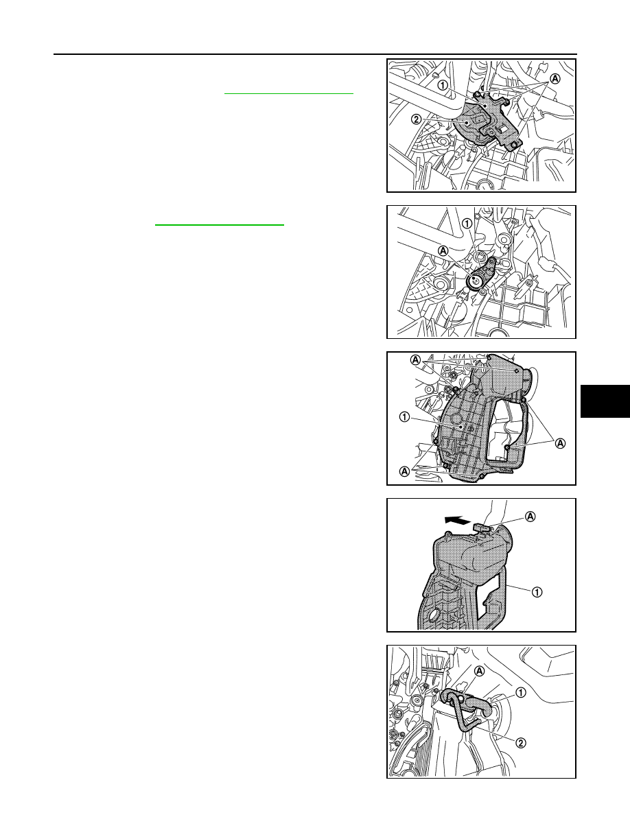
11. Remove mounting screws (A), and then remove mode door
motor bracket (1).
12. Remove main link (2). Refer to
.
13. Remove mounting screw (A), and then remove max. cool door
link (1). Refer to
.
14. Remove mounting screws (A), and then remove evaporator
cover (1).
15. Remove connector (A) from evaporator cover (1) (as shown in
the figure).
16. Remove mounting bolt (A), and then remove low-pressure pipe
1 (1) and high-pressure pipe 2 (2).
CAUTION:
Cap or wrap the joint of the A/C piping and expansion valve
with suitable material such as vinyl tape to avoid the entry
of air.
JPIIA0694ZZ
JPIIA0695ZZ
JPIIA0696ZZ
JSIIA1270ZZ
JPIIA0697ZZ
HA-46
< REMOVAL AND INSTALLATION >
[VQ35HR]
COOLER PIPE AND HOSE
INSTALLATION
Installation is basically the reverse order of removal.
CAUTION:
• Replace O-rings with new ones. Then apply compressor oil to them when installing.
• Female-side piping connection is thin and easy to deform. Slowly insert the male-side piping
straight in axial direction.
• Insert piping securely until a click is heard.
• After piping connection is completed, pull male-side piping by hand to make sure that connection
does not come loose.
• Check for leakages when recharging refrigerant.

CONDENSER
HA-47
< REMOVAL AND INSTALLATION >
[VQ35HR]
C
D
E
F
G
H
J
K
L
M
A
B
HA
N
O
P
CONDENSER
Exploded View
INFOID:0000000005249914
CONDENSER
CONDENSER : Removal and Installation
INFOID:0000000005249915
REMOVAL
1.
Remove condenser pipe assembly. Refer to
2.
Remove ambient sensor. Refer to
.
3.
Remove gas sensor (WITH ACCS). Refer to
.
4.
Remove harness clips (A).
5.
Remove mounting bolts (B) and nut (C), and then remove hood
lock stay assembly (1).
1.
Condenser upper bracket (left)
2.
Condenser upper bracket (right)
3.
Refrigerant pressure sensor
4.
O-ring
5.
Liquid tank
6.
Liquid tank bracket
7.
Bracket
8.
Condenser
9.
Condenser lower bracket (right)
10. Condenser lower bracket (left)
11.
Condenser pipe assembly
Refer to
JSIIA1373GB
JSIIA1271ZZ
HA-48
< REMOVAL AND INSTALLATION >
[VQ35HR]
CONDENSER
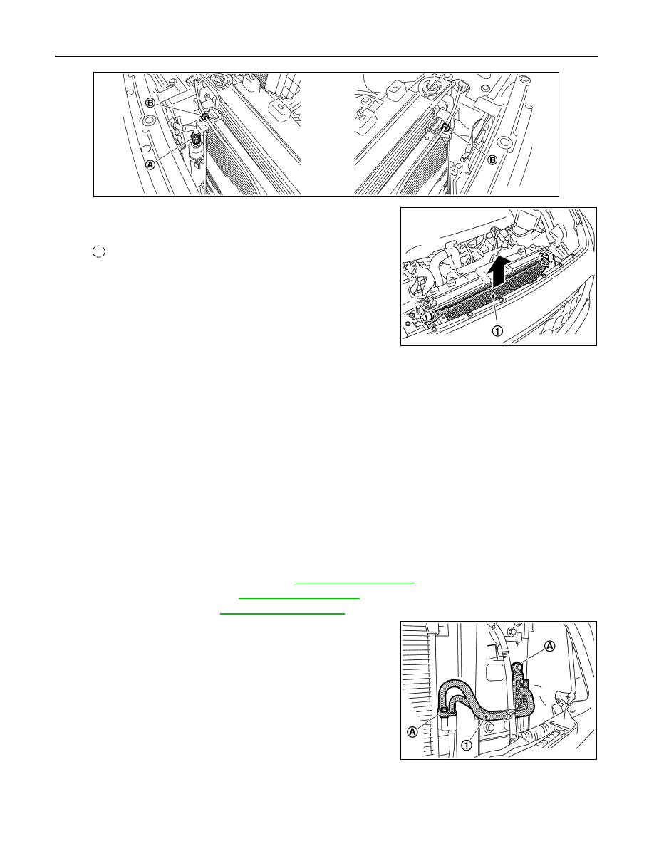
6.
Disconnect refrigerant pressure sensor connector (A) and harness clips (B).
7.
Pull condenser (1) upward of vehicle, and then remove con-
denser (as shown in the figure).
CAUTION:
Be careful not to damage core surface of condenser.
INSTALLATION
Installation is basically the reverse order of removal.
CAUTION:
• Replace O-rings with new ones. Then apply compressor oil to them when installing.
• Female-side piping connection is thin and easy to deform. Slowly insert the male-side piping
straight in axial direction.
• Insert piping securely until a click is heard.
• After piping connection is completed, pull male-side piping by hand to make sure that connection
does not come loose.
• Check for leakages when recharging refrigerant.
CONDENSER PIPE ASSEMBLY
CONDENSER PIPE ASSEMBLY : Removal and Installation
INFOID:0000000005249916
REMOVAL
1.
Use a refrigerant collecting equipment (for HFC-134a) to discharge the refrigerant.
2.
Remove air cleaner case (bank 2). Refer to
.
3.
Remove air duct (inlet). Refer to
4.
Remove front grille. Refer to
.
5.
Remove mounting bolts (A) from condenser pipe assembly (1).
JSIIA1272ZZ
:
Pawl
JSIIA1273ZZ
JSIIA1274ZZ
Нет комментариевНе стесняйтесь поделиться с нами вашим ценным мнением.
Текст