Infiniti FX35, FX50 (S51). Manual — part 1395
MWI
UNIFIED METER AND A/C AMP.
MWI-99
< ECU DIAGNOSIS INFORMATION >
C
D
E
F
G
H
I
J
K
L
M
B
A
O
P
NOTE:
Some items are not available according to vehicle specification.
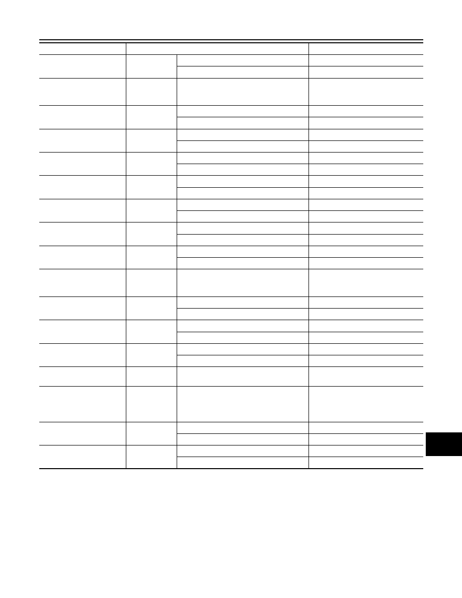
TERMINAL LAYOUT
AT S MODE SW
Ignition switch
ON
Snow mode switch pressed
On
Snow mode switch not pressed
Off
AT P MODE SW
Ignition switch
ON
NOTE:
This item is displayed, but cannot be moni-
tored.
Off
M RANGE SW
Ignition switch
ON
Selector lever manual mode position
On
Other than the above
Off
NM RANGE SW
Ignition switch
ON
Selector lever manual mode position
Off
Other than the above
On
AT SFT UP SW
Ignition switch
ON
Selector lever + position
On
Other than the above
Off
AT SFT DWN SW
Ignition switch
ON
Selector lever – position
On
Other than the above
Off
ST SFT UP SW
Ignition switch
ON
Paddle shifter switch up operation
On
Other than the above
Off
ST SFT DWN SW
Ignition switch
ON
Paddle shifter switch down operation
On
Other than the above
Off
COMP F/B SIG
Ignition switch
ON
A/C compressor activation condition
On
A/C compressor deactivation condition
Off
4WD LOCK SW
Ignition switch
ON
NOTE:
This item is displayed, but cannot be moni-
tored.
Off
PKB SW
Ignition switch
ON
Parking brake switch ON
On
Parking brake switch OFF
Off
BUCKLE SW
Ignition switch
ON
Seat belt not fastened
On
Seat belt fastened
Off
BRAKE OIL SW
Ignition switch
ON
Brake fluid level switch ON
On
Brake fluid level switch OFF
Off
DISTANCE
[km/h]
Ignition switch
ON
—
Possible driving distance calculated by
unified meter and A/C amp.
OUTSIDE TEMP
[
°
C] or [
°
F]
Ignition switch
ON
—
Equivalent to ambient temperature
NOTE:
This may not match the indicated val-
ue on the information display.
FUEL LOW SIG
Ignition switch
ON
Low-fuel warning signal output
On
Low-fuel warning signal not output
Off
BUZZER
Ignition switch
ON
Buzzer ON
On
Buzzer OFF
Off
Monitor Item
Condition
Value/Status
MWI-100
< ECU DIAGNOSIS INFORMATION >
UNIFIED METER AND A/C AMP.
PHYSICAL VALUES
JSNIA0097ZZ
Terminal No.
(Wire color)
Description
Condition
Value
(Approx.)
+
–
Signal name
Input/
Output
5
(L)
Ground
Manual mode shift up sig-
nal
Input
Ignition
switch
ON
Selector lever UP operation
0 V
Other than the above
12 V
6
(O)
Ground
Paddle shifter up signal
Input
Ignition
switch
ON
Paddle shifter up operation
0 V
Other than the above
12 V
7
(GR)
Ground
Communication signal
(AMP.
→
METER)
Output
Ignition
switch
ON
—
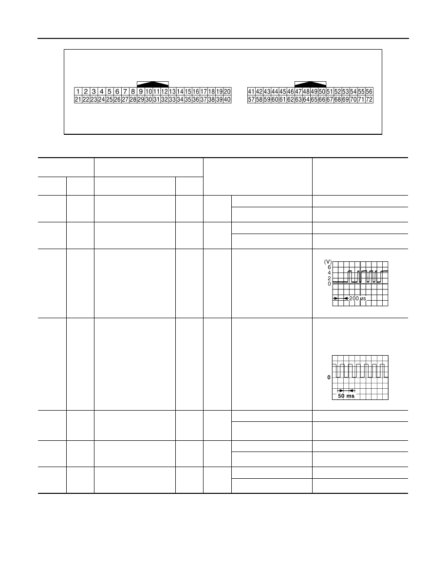
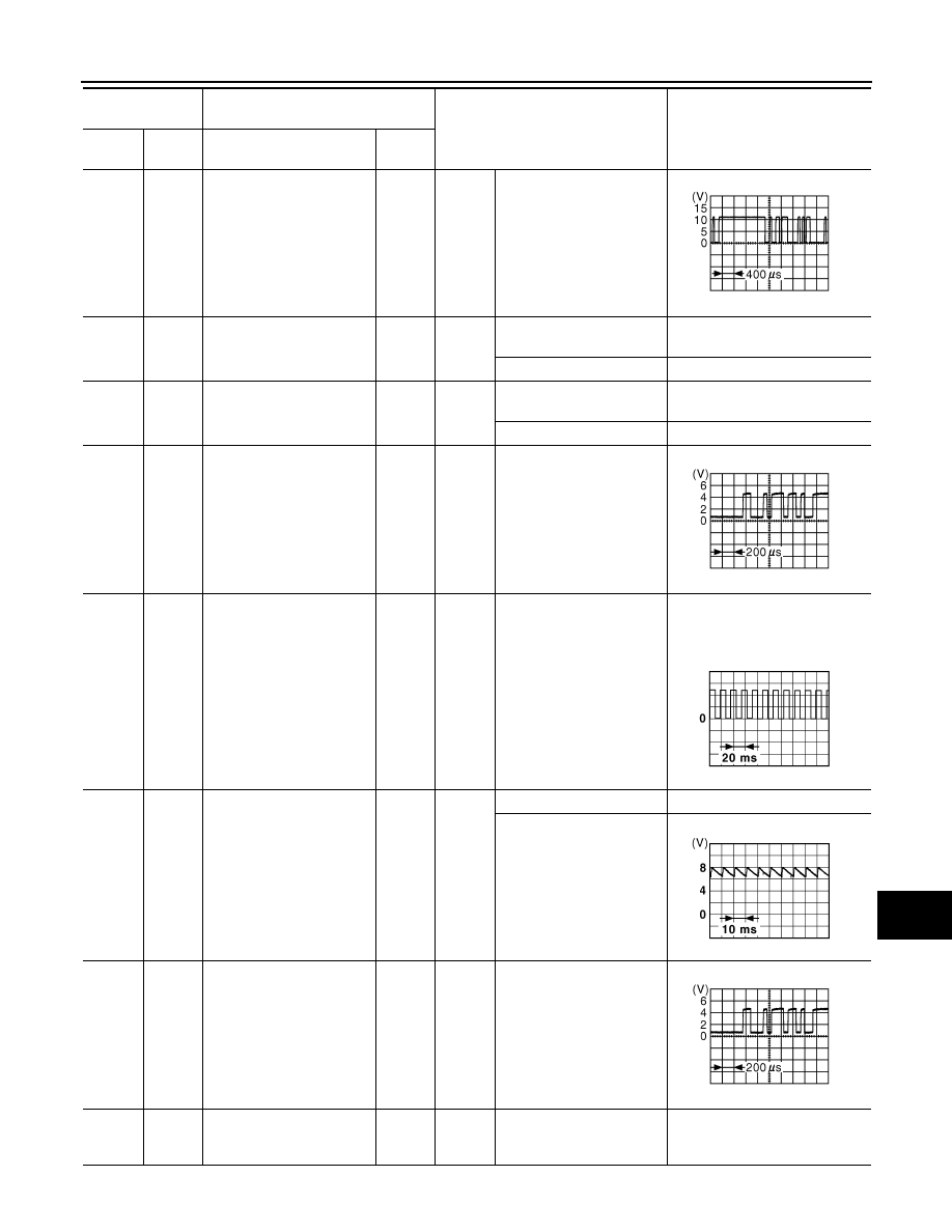
8
(L)
Ground
Vehicle speed signal output
(2-pulse)
Output
Ignition
switch
ON
Speedometer operated
[When vehicle speed is ap-
prox. 40 km/h (25 MPH)]
NOTE:
The maximum voltage varies de-
pending on the specification
(destination unit).
9
(SB)
Ground
Seat belt buckle switch sig-
nal (driver side)
Input
Ignition
switch
ON
When seat belt is fastened
12 V
When seat belt is not fas-
tened
0 V
10
(W)
Ground
Manual mode signal
Input
Ignition
switch
ON
Selector lever DS position
0 V
Other than the above
12 V
11
(G)
Ground
Non-manual mode signal
Input
Ignition
switch
ON
Selector lever DS position
12 V
Other than the above
0 V
JSNIA0027GB
JSNIA0015GB
MWI
UNIFIED METER AND A/C AMP.
MWI-101
< ECU DIAGNOSIS INFORMATION >
C
D
E
F
G
H
I
J
K
L
M
B
A
O
P
14
(BR)
Ground
Communication signal
(LCD
→
AMP.)
Input
Ignition
switch
ON
—
25
(V)
Ground
Manual mode shift down
signal
Input
Ignition
switch
ON
Selector lever down opera-
tion
0 V
Other than the above
12 V
26
(G)
Ground
Paddle shifter down signal
Input
Ignition
switch
ON
Paddle shifter down opera-
tion
0 V
Other than the above
12 V
27
(LG)
Ground
Communication signal
(METER
→
AMP.)
Input
Ignition
switch
ON
—
28
(R)
Ground
Vehicle speed signal output
(8-pulse)
Output
Ignition
switch
ON
Speedometer operated
[When vehicle speed is ap-
prox. 40 km/h (25 MPH)]
NOTE:
The maximum voltage varies de-
pending on the specification
(destination unit).
30
(V)
Ground
Parking brake switch signal
Input
Ignition
switch
ON
Parking brake ON
0 V
Parking brake OFF
34
(Y)
Ground
Communication signal
(AMP.
→
LCD)
Output
Ignition
switch
ON
—
41
(V)
Ground
ACC power supply
Input
Ignition
switch
ACC
—
Battery voltage
Terminal No.
(Wire color)
Description
Condition
Value
(Approx.)
+
–
Signal name
Input/
Output
JSNIA0028GB
JSNIA0027GB
JSNIA0012GB
JSNIA0007GB
JSNIA0027GB
MWI-102
< ECU DIAGNOSIS INFORMATION >
UNIFIED METER AND A/C AMP.
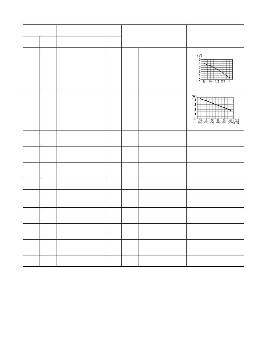
42
(Y)
Ground
Fuel level sensor signal
Input
Ignition
switch
ON
—
45
(P)
Ground
Ambient sensor signal
Input
—
—
53
(G)
Ground
Ignition signal
Input
Ignition
switch
ON
—
Battery voltage
54
(O)
Ground
Battery power supply
Input
Ignition
switch
OFF
—
Battery voltage
55
(B)
Ground
Ground
—
Ignition
switch
ON
—
0 V
56
(L)
Ground
CAN-H
—
—
—
—
57
(W)
Ground
Brake fluid level switch sig-
nal
Input
Ignition
switch
ON
Brake fluid level is normal.
5 V
The brake fluid level is low-
er than the low level
0 V
58
(B)
Ground
Fuel level sensor signal
ground
—
Ignition
switch
ON
—
0 V
61
(BR)
Ground
Ambient sensor signal
ground
—
Ignition
switch
ON
—
0 V
71
(B)
Ground
Ground
—
Ignition
switch
ON
—
0 V
72
(P)
Ground
CAN-L
—
—
—
—
Terminal No.
(Wire color)
Description
Condition
Value
(Approx.)
+
–
Signal name
Input/
Output
SKIB8867E
JSNIA0014GB
Нет комментариевНе стесняйтесь поделиться с нами вашим ценным мнением.
Текст