Infiniti FX35, FX50 (S51). Manual — part 136
AV
STEERING SWITCH SIGNAL B CIRCUIT
AV-317
< DTC/CIRCUIT DIAGNOSIS >
[NAVIGATION (SINGLE MONITOR)]
C
D
E
F
G
H
I
J
K
L
M
B
A
O
P
STEERING SWITCH SIGNAL B CIRCUIT
Description
INFOID:0000000005475941
Transmits the steering switch signal to AV control unit.
Diagnosis Procedure
INFOID:0000000005475942
1.
CHECK STEERING SWITCH SIGNAL B CIRCUIT
1.
Disconnect AV control unit connector and spiral cable connector.
2.
Check continuity between AV control unit harness connector and spiral cable harness connector.
3.
Check continuity between AV control unit harness connector and ground.
Is the inspection result normal?
YES
>> GO TO 2.
NO
>> Repair harness or connector.
2.
CHECK SPIRAL CABLE
Check spiral cable.
Is the inspection result normal?
YES
>> GO TO 3.
NO
>> Replace spiral cable. Refer to
.
3.
CHECK AV CONTROL UNIT VOLTAGE
1.
Connect AV control unit connector and spiral cable connector.
2.
Turn ignition switch ON.
3.
Check voltage between AV control unit harness connector.
Is the inspection result normal?
YES
>> GO TO 4.
NO
>> Replace AV control unit. Refer to
4.
CHECK STEERING SWITCH
1.
Turn ignition switch OFF.
2.
Check steering switch. Refer to
AV-317, "Component Inspection"
Is the inspection result normal?
YES
>> INSPECTION END
NO
>> Replace steering switch. Refer to
Component Inspection
INFOID:0000000005475943
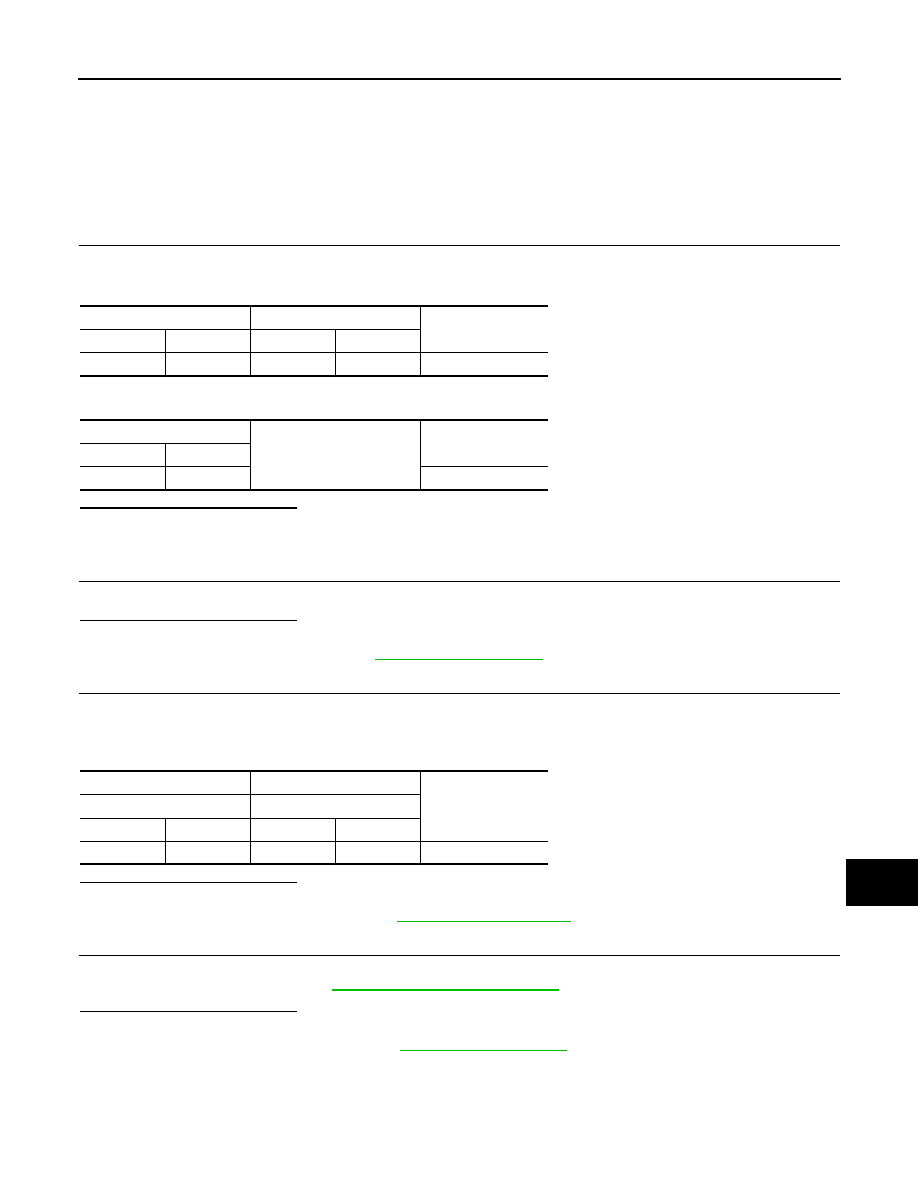
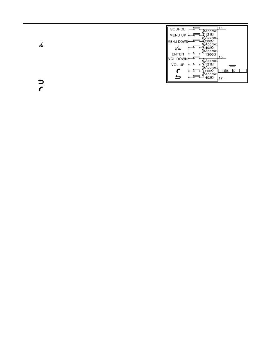
Measure the resistance between the steering switch connector terminals 14 to 17 and 15 to 17.
AV control unit
Spiral cable
Continuity
Connector
Terminal
Connector
Terminal
M208
16
M36
31
Existed
AV control unit
Ground
Continuity
Connector
Terminal
M208
16
Not existed
(+)
(
−
)
Voltage
(Approx.)
AV control unit
AV control unit
Connector
Terminal
Connector
Terminal
M208
16
M208
15
5.0 V
AV-318
< DTC/CIRCUIT DIAGNOSIS >
[NAVIGATION (SINGLE MONITOR)]
STEERING SWITCH SIGNAL B CIRCUIT
Standard
Between terminals 14 and 17
ENTER switch ON
: 2003 – 2043
Ω
switch ON
: 716 – 730
Ω
MENU DOWN switch ON
: 318 – 324
Ω
MENU UP switch ON
: 120 – 122
Ω
SOURCE switch ON
: 0
Ω
Between terminals 15 and 17
switch ON
: 716 – 730
Ω
switch ON
: 318 – 324
Ω
VOL UP switch ON
: 120 – 122
Ω
VOL DOWN switch ON
: 0
Ω
JSNIA0112GB
AV
STEERING SWITCH GROUND CIRCUIT
AV-319
< DTC/CIRCUIT DIAGNOSIS >
[NAVIGATION (SINGLE MONITOR)]
C
D
E
F
G
H
I
J
K
L
M
B
A
O
P
STEERING SWITCH GROUND CIRCUIT
Description
INFOID:0000000005475944
Transmits the steering switch signal to AV control unit.
Diagnosis Procedure
INFOID:0000000005475945
1.
CHECK STEERING SWITCH SIGNAL GND CIRCUIT
1.
Disconnect AV control unit connector and spiral cable connector.
2.
Check continuity between AV control unit harness connector and spiral cable harness connector.
3.
Connect AV control unit connector.
Is the inspection result normal?
YES
>> GO TO 2.
NO
>> Repair harness or connector.
2.
CHECK SPIRAL CABLE
Check spiral cable.
Is the inspection result normal?
YES
>> GO TO 3.
NO
>> Replace spiral cable. Refer to
.
3.
CHECK GROUND CIRCUIT
1.
Connect AV control unit connector.
2.
Check continuity between AV control unit harness connector and ground.
Is the inspection result normal?
YES
>> GO TO 4.
NO
>> Replace AV control unit. Refer to
4.
CHECK STEERING SWITCH
1.
Turn ignition switch OFF.
2.
Check steering switch. Refer to
AV-319, "Component Inspection"
Is the inspection result normal?
YES
>> INSPECTION END
NO
>> Replace steering switch. Refer to
Component Inspection
INFOID:0000000005475946
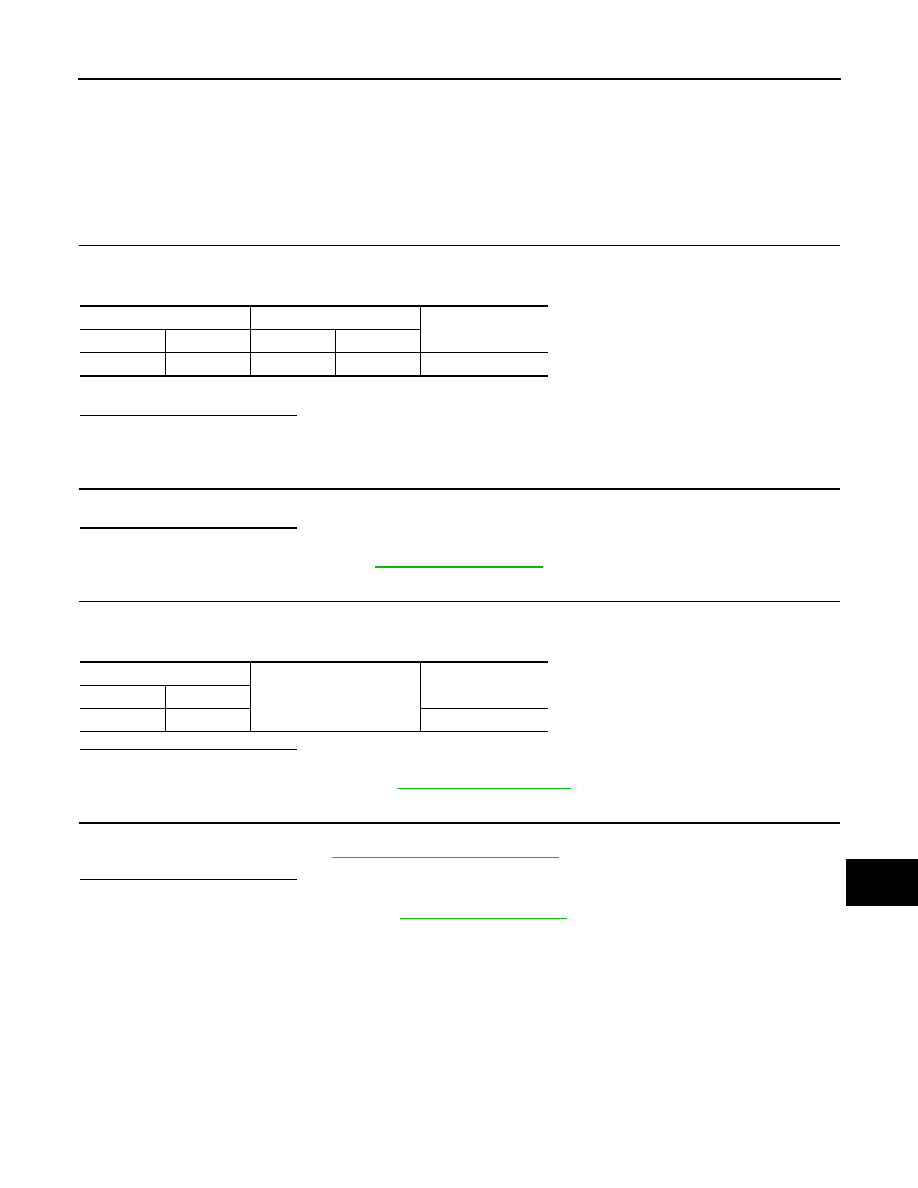
Measure the resistance between the steering switch connector terminals 14 to 17 and 15 to 17.
AV control unit
Spiral cable
Continuity
Connector
Terminal
Connector
Terminal
M208
15
M36
33
Existed
AV control unit
Ground
Continuity
Connector
Terminal
M208
15
Not existed

AV-320
< DTC/CIRCUIT DIAGNOSIS >
[NAVIGATION (SINGLE MONITOR)]
STEERING SWITCH GROUND CIRCUIT
Standard
Between terminals 14 and 17
ENTER switch ON
: 2003 – 2043
Ω
switch ON
: 716 – 730
Ω
MENU DOWN switch ON
: 318 – 324
Ω
MENU UP switch ON
: 120 – 122
Ω
SOURCE switch ON
: 0
Ω
Between terminals 15 and 17
switch ON
: 716 – 730
Ω
switch ON
: 318 – 324
Ω
VOL UP switch ON
: 120 – 122
Ω
VOL DOWN switch ON
: 0
Ω
JSNIA0112GB
Нет комментариевНе стесняйтесь поделиться с нами вашим ценным мнением.
Текст